No more secrets Part 11: Is this a divisor or a counter?
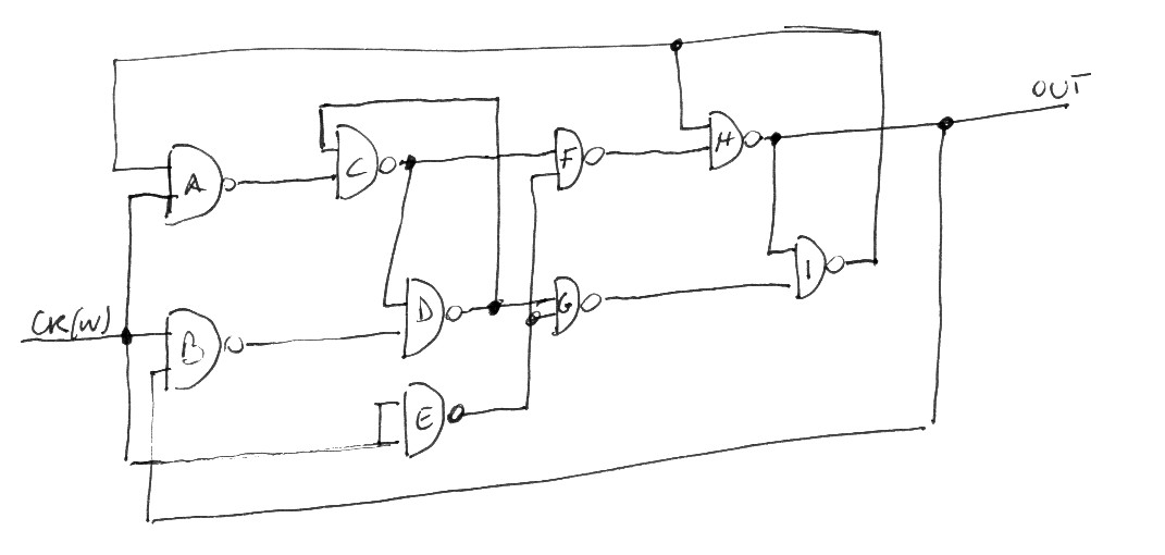
The answer is "both". The circuit presented in this section is, at the same time, a circuit to divide a frequency by two and an element to build a counter, i.e. a circuit which counts. In fact, our circuit will switches its status each time the input value goes from one to zero (on the falling edge of the binary signal, in technical jargon). Here is the circuit:
ck -> ABEE
A -> C
B -> D
C -> DF
D -> CG
E -> FG
F -> H
G -> I
H -> BI out
I -> AH
To test this circuit, connect the input ck to the master clock and plug in two leds, one to the master clock output and the other to the output (out) of our circuit. If everything works properly you will see that the led connected to the output switches its state, zero to one or one to zero, when the other led turns off. So, if the master clock led is flashing at about 1Hz, the other led has a frequency of 0.5Hz. On the other hand if we take note to the configurations of the two leds we will get the following table:
out ck
0   0
0   1
1   0
1   1
... then the sequence restarts from its beginning. This is a two bit counter, it count from zero up to three and then overflows and restarts from zero (wraparound, in technicalese).
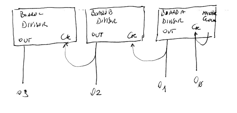
Using more breadboards it is possible to implement counters using more bits. The divisors must be chained: the LSB of the counter is a master clock of a board, connect it to the ck input on the same board and you will get the second-LSB of the result. Then connect the out of this board to the ck of the following one and so on up to the number of bits of the counter. Three breadboards permit to implement a four bit counter.
The first out signal provides divides the frequency of the clock by two, and in the same way all the other divisors further divide the resulting frequency by two.
The output of this circuit can be visualized by the following table:
o3 o2 o1 o0=ck
0  0  0  0
0  0  0  1
0  0  1  0
0  0  1  1
0  1  0  0
0  1  0  1
0  1  1  0
0  1  1  1
1  0  0  0
1  0  0  1
1  0  1  0
1  0  1  1
1  1  0  0
1  1  0  1
1  1  1  0
1  1  1  1
A four traces oscilloscope would show the following traces:


