Differenze tra le versioni di "A Fridge Magnet"
| Riga 33: | Riga 33: | ||
[[File:fridge3.jpg|300px]] | [[File:fridge3.jpg|300px]] | ||
| + | |||
| + | This card is the only hardware part than needs to be soldered. The current version, as shown in the picture here above, uses a JeeLabs proto board | ||
| + | and insulated copper wired. | ||
| + | |||
| + | Here is the table of the connections: | ||
| + | |||
| + | <pre> | ||
| + | Display Signal Connected to: AtMega pin: Equivalent | ||
| + | Connector (JeeNode) "Arduino pin#" | ||
| + | |||
| + | 1 GND GND(pin 3 any P port) GND GND | ||
| + | 2 3.3V +3V(pin 4 any P port) +3.3V +3.3V | ||
| + | 3 SCLK SCK(pin 3 SPI/ISP) SCLK/PB5 pin 19 13 | ||
| + | 4 MOSI MOSI(pin 4 SPI/ISP) MOSI/PB3 pin 17 11 | ||
| + | 5 MISO MISO(pin 1 SPI/ISP) MISO/PB4 pin 18 12 | ||
| + | 6 SSEL PB0 pin 14 8 | ||
| + | 7 Busy PD7 pin 13 7 | ||
| + | 8 BorderCtl PD3 pin 5 3 | ||
| + | 9 SCL SCL(pin 5 PWR/SEL/I2C) SCL/PC5 pin 28 A6 | ||
| + | 10 SDA SDA(pin 4 PWR/SEL/I2C) SDA/PC4 pin 27 A5 | ||
| + | 11 PWM | ||
Versione delle 12:15, 16 mag 2013
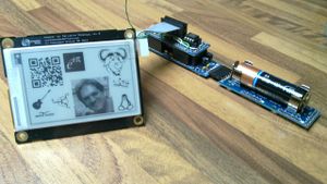
This is the implementation of the idea to create an electronic fridge magnet.
What is that?
- It is a battery operated Display
- A radio wireless connection provides the contents to show
It can be used as a "Internet of Things" implementation of a fridge magnet to show important or interesting information for the family, but can be used as a price/special offer label on the front side of shop shelves.
Here is a picture of the prototype to whet your appetite:
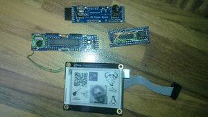
The components used in this prototype are:
- a JeeNode v6 (18.5 euros)
- an e-paper display (29 euros)
- a 23k236 32KB RAM (1.61 euro)
- a jeelabs proto board (3.50 euros)
- AA Power Board (14.5 euros)
- pin stripes, copper wire, ...
- patience (unvaluable)
The total cost for a unit is around 70 euros (plus shipping costs from several suppliers etc).
The following parts are needed to upload the software and to send the images to our display (or to several displays):
- JeeLabs USB interface (13.5 euros)
- another JeeNode v6 (18.5 euros) or a JeeLink (32.5 euros).
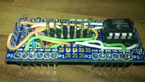
RAM and wiring card
This card is the only hardware part than needs to be soldered. The current version, as shown in the picture here above, uses a JeeLabs proto board and insulated copper wired.
Here is the table of the connections:
Display     Signal     Connected to:         AtMega pin:        Equivalent
Connector              (JeeNode)                                "Arduino pin#"

1           GND        GND(pin 3 any P port)   GND              GND
2           3.3V       +3V(pin 4 any P port)  +3.3V             +3.3V
3           SCLK       SCK(pin 3 SPI/ISP)      SCLK/PB5 pin 19  13
4           MOSI       MOSI(pin 4 SPI/ISP)     MOSI/PB3 pin 17  11
5           MISO       MISO(pin 1 SPI/ISP)     MISO/PB4 pin 18  12
6           SSEL                               PB0 pin 14       8
7           Busy                               PD7 pin 13       7
8           BorderCtl                          PD3 pin 5        3
9           SCL        SCL(pin 5 PWR/SEL/I2C)  SCL/PC5 pin 28   A6
10          SDA        SDA(pin 4 PWR/SEL/I2C)  SDA/PC4 pin 27   A5
11          PWM


