A DIY touch probe for my Wasp 3D printer
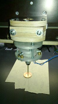
This posting provides the recipe to build a touch probe. This kind of tool may convert your 3D printer into a 3D scanner (for carved surfaces), or it can be used to measure objects.
This project consists of three parts:
- Hardware
- Electronics
- Software support
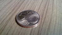
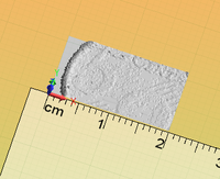
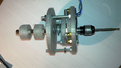
I'll put some pictures here just to ignite your curiosity.
This is a short movie showing the probe in action:
== Part 1: Hardware ==
The main challenge of my touch probe is to use only 3D printed parts and standard mechanical components which can be bought off-the-shelf from hardware shops.
The probe consists of:
- A) a fixed support, which can be mounted as a tip for the micro-drill or fixed to the wasp by an adapter.
- B) a floating structure, rigidly attached to the mandrel where different sensing tips can be mounted. The floating structure has three metallic cylinders which close contacts on the fixed structure. The stable position is guaranteed by a spring and by the geometry of the entire structure. When the sensing tip touches something (on top or on any side) one of the three contacts get opened, signaling in this way the control electronics and the software.
- C) (optional) a support for the Wasp 3D printer
The list of materials for A include:
- Two printed parts: lowerfix.stl and topfix.stl
- #1 M3x20 bolt
- #6 M3x8 bolts
- #6 M3 brass dome nuts
- #3 M3x40 bolts
- #10 M3 nuts
- ca. 2m of phone pair wire
- a 3.5mm mono jack plug
- a spring (a pushing spring ca. 10mm wide and 10mm high)
The dome nuts must be mounted by the M3x8 bolts on lowerfix using the three groups of paired holes. These three pairs of nuts will be used as three "normally closed" buttons, connected in series. For this, use short chunks of the phone wire to connect the nuts as shown here:
The remaining part of the phone wire can be soldered to the jack terminals (one wire per terminal, the order does not matter).
Now the other three holes of lowerfix can be used to connect it with topfix. Insert the three M3x40 bolts in the remaining holes in lowerfix (the heads must be in the same side of the M3x8) and fix them using three M3 nuts. Put other three M3 nuts on the long threaded ends of the M3x40 bolts. The topfix part will be fixed to these bolts using three nuts below and three nuts on the upper side. The topfix part can be raised or lowered in this way to tune the right strength of the spring. Do not mount topfix yet. Just put the M3x20 bolt in the central hole of topfix, its head on the side where there is a notch. (This notch keeps the spring in place). Fix this bolt by a M3 nut on the other side. I suggest to add two suitable washers on both sides to enlarge the contact surface and provide a stronger fixation, less prone to vibrations and torsions. This bolt will be used as a shaft to fix the probe to the mandrel of a micro drill (my Wasp uses a Proxxon LBS/E). Alternatively the probe can be fixed directly to a wasp support (e.g. by the "C" optional component).
The part B comes in two "flavours" (or options) I wanted my probe to have a mandrel, in order to mount different probe tips for different usage scenarios (longer, shorter, thinner, thicker..) It was quite hard to find supports for standard mandrels. Proxxon connects its mandrels to threaded tubes M8x0.75. There are two kinds of mandrels available: Three-jaw drill chuck (Proxxon's part.no 28941) Collet set (part.no 28940). Obviously there may be many third party cheaper clones on e-bay.
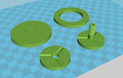
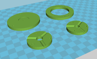
This picture shows the 3D printed parts needed for part A and part B first option:
The first option for part B uses the three-jaw drill chuck. I was not able to locate a compatible threaded tube on the market, so I decided to 3D print a threaded "pole". It works, but a plastic thread deteriorates quite quickly. If you change the probe tips very often, maybe you'll have to print the part again.
The materials for both "flavours" is the following:
- #3 M3x20 bolts
- #3 M3 nuts
- #3 5mm Shelf Pins (x16mm) (#3 M5x20 bolts could be used instead, but the shelf Pins work better, they are smooth, so they provide a better electrical contact)
Flavour A needs also:
- a Three-jaw drill chuck
- Two 3D printed parts: floatingtopnohole and floatingokh9
Insert the threaded end of floatingtopnohole into the floatingokh9 hole. Install the three M3 bolts in the holes and the nuts on the other side. Put the three pins laterally so that the two plastic parts can block them like sousages in a sandwitch. I suggest to scrap the shelf pins by a piece of abrasive paper to have a better contact.
Install the drill chuck. The plastic made threaded screw is not perfect, so the first time you'll have to fasten and release it several times, each time doing some more turns before the chuck can use all the thread it needs.
If you decided for this option you are done.
The other option for B uses the collet. It is a better solution, more durable.
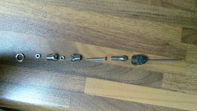
These are the components for A and B second option:
For this option you need:
- a Collet set (including the clumping nut)
- two concave metallic led holders for 5mm leds ;-) (e.g. this: http://www.graziacomponenti.it/index.php?id_product=5680&controller=product)
- a M3x20 bolt, two M3 nuts.
- Two 3D printed parts: floatingh8, floatingh10.
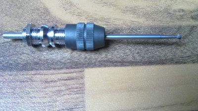
It happens that many metallic led holders use the same threading pitch of the Proxxon collars... I joined together two led holders using a M3x20 bolt and two nuts. These are the components: the two led holders, the bolt and nuts to join them together, the led holder hexagonal nut, the collar and chuck by Proxxon.
The components in the picture belong to a second prototype I built. Actually, these led holders have a shorter threaded part than those used in the prototype depicted in the other snapshots. Obviously the longest threaded part the better, as the chuck can be fixed in a better way.
Insert the bolt in a led holder and fix it using a nut, insert the other led holder (reversed with respect to the other) and fix it with the other nut. The result is a similar to a threaded bar.
This bar can be fixed to floatingh8 using one of the hexagonal nut provided with the led holders. It is possible to mount floatingh8 as the upper part of B and mount the lead holder bar such that it passes through the hole in floatingh10 or viceversa, floatingh8 as the bottom side of B. The former is more compact. I decided for the latter as it permits to grasp by thumb and index the thicker part of the led-holders-"bar" when I want to fasten or unfasten probing tips.
The mounting of the shelf bins as sousages dropping out from hot-dogs ;-) has already been described for the other option of B.
Now whatever option you have chosen for B it is possible to position it into A, put the spring in place, and close topfix on the top as a cover using the three M3 nuts to fix it. The three shelf pins must be positioned between the brass dome nuts to close the circuit.
Now you can test the probe using a digital multimeter. Set the multimeter to 2K or 20K ohm (it does not really matter), and connect the probes to the two contacts of the jack. You should read zero (closed circuit). As soon as you touch the mandrel of the floating part the circuit should be open (the multimeter should show infinite)
For C I have used a 4cm hexagonal pcb spacer and two printed support (so that the spacer can be grabbed by the micromot support of the Wasp).
The hardware of the probe is complete.
Part 2: Electronics
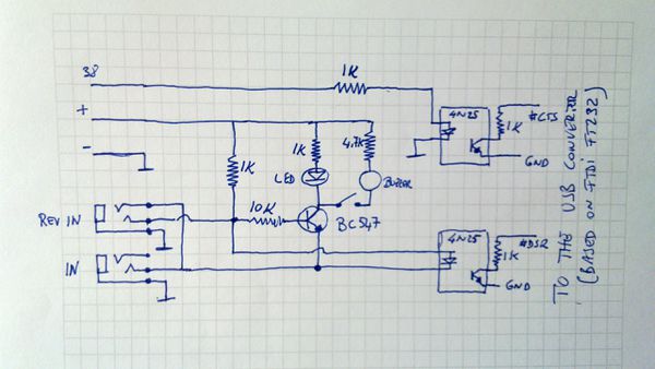
The challenges for the design of the interfacing circuit were:
- to have a minimalistic design (the simpler the better)
- to support usb connection to the computer (rs232 ports are quite rare nowadays)
- to be a general purpose tool: it need to support both our probe (normally closed circuit) and other probes (normally opened). Two crocodile clamps connected to a CNC bit and to a conductive surface can be a "probe", too.
- to have a led and a beeper as feedback outputs. The beeper could be disabled when it is not required.
- to use optocoupler to keep the 3D printer and the USB input as independent circuits
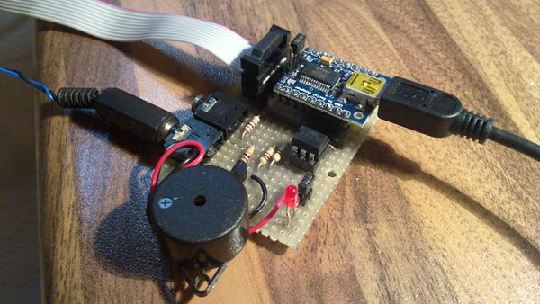
Here is the circuit.
It is connected to the EXT2 connector of the Wasp 3D printer, or more precisely to the EXT2 port of the Ultimaker board inside the Wasp.
There are some tricks:
- There are two jack sockets: the probe's plug can be inserted in one of these two sockets. One is for "normally open" probes, the other for "normally closed" probes. The trick is done using stereo sockets for mono plugs: mono plugs short circuit the shield and the middle ring contacts of the socket. I use this property as a switch to invert the logic.
- There are wonderful ICs implementing serial communications on USB like FT232 available on the market. Unfortunately they are hard to solder as they are surface mounted. Anyway there are a lot of break-out boards available, for this circuit we need one of them providing access to the the DTR and CTS pins of the IC. I used this: http://www.microbot.it/product/18/USB-to-Serial-Adapter-with-FT232RL.html but this should work as well: https://www.sparkfun.com/products/718
- We are interested on two binary signals: one is the signal from the probe and the other is provided by the 3D printer (Arduino's GPIO 38 from the EXT2 socket of the Ultimaker board). We'll use this signal to acknowledge to have reached each testing x, y, z position prior to check the output of the probe. Instead of a specific microcontroller, I decided to use two RS-232 control signals (DTR and CTS) to get the two binary inputs.
- The transistor drives the feedback led and buzzer, so that the current to the opto-coupler is constant despite of the activation/deactivation of the buzzer.
Part 3: Software
I wrote an experimental python 3 program to drive the scanner.
It is just a proof-of-concept. It provides a g-code line terminal plus it supports some scanning commands.
The most important feature is the emergency exit ctrl-C. If you send a wrong g-code command and the motors of your 3D printer are in trouble because the probe hits a mechanical boundary, promptly press ctrl-C. This resets the 3D printer completely and immediately aborts the current operation.
For the sake of completeness, the Marvin firmware running on the Wasp printer does not implement the M112 emergency stop, so the trick has been implemented by toggling off and on two control signals (DTR/RTS). This is a built-in reset command for the arduino board inside the Wasp printer.
You have to patch the python serial library to be able to use the 250000baud speed (which is non-standard). In Debian the file to patch is: /usr/lib/python3/dist-packages/serial/serialposix.py and the patch is this: http://sourceforge.net/p/pyserial/patches/_discuss/thread/ed3fb0de/f4fd/attachment/pyserial.patch (there is a local copy here )
At the beginning this python program checks is the printer and the probe are correctly connected. At one point it asks the operator to touch the probe. It would be quite dangerous if the probe is not correctly connected as the scan would not stop when the probe touches the surface.
All the G-code command will be prompted and sent to the printer. The commands for the probe has a # prefix.
 #help shows the list of available commands
 #status shows the status of the variables
 #set permits to set a variable, e.g. #set xmin 0
 #getz returns the Z level in the current position
 #scan starts an area scan: this scan always returns to the zmax level,
       so it is extremely slow
 #lscan starts an area scan: this scan uses the side touch, so it always
       stays close to the surface, it is quite slow (which is way better than
       extremely slow, but the whole process is slow anyway)
 #outfile defines an output file for scan results. It is a csv file,
       each row provides the x, y, z coordinates of one point in the 3d space.
       The field separator is a semi-colon.
