A Fridge Magnet
This is the implementation of the idea to create an electronic fridge magnet.
What is that?
- It is a battery operated Display
- A radio wireless connection provides the contents to show
It can be used as a "Internet of Things" implementation of a fridge magnet to show important or interesting information for the family, but can be used as a price/special offer label on the front side of shop shelves.
Features:
- It is possible to connect up to 212*31=6572 displays to the same transmitter and update them independently (several displays sharing the same address will show the same contents).
- Using an optimized version of the code (currently under development) the circuit can work for monthes on a single battery. The display is bi-stable so it can turned off, the entire circuit can be put in sleep mode for the most part of the time.
- Any battery able to give a voltage in the range 1V - 5.5V can be usedas the power supply for the circuit, e.g. a lithium 3v battery (CR2032).
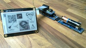
Here is a picture of the prototype to whet your appetite:
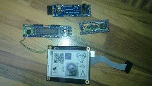
The components used in this prototype are:
- a JeeNode v6 (18.5 euros)
- an e-paper display (29 euros)
- a 23k236 32KB RAM (1.61 euro)
- a jeelabs proto board (3.50 euros)
- AA Power Board (14.5 euros)
- pin stripes, copper wire, ...
- patience (unvaluable)
The total cost for a unit is around 70 euros (plus shipping costs from several suppliers etc).
The following parts are needed to upload the software and to send the images to our display (or to several displays):
- JeeLabs USB interface (13.5 euros)
- another JeeNode v6 (18.5 euros) or a JeeLink (32.5 euros).
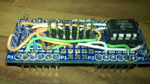
RAM and wiring card
This card is the only hardware part than needs to be soldered. The current version, as shown in the picture here above, uses a JeeLabs proto board and insulated copper wired.
Here is the table of the connections:
Display     Signal     Connected to:         AtMega pin:        Equivalent
Connector              (JeeNode)                                "Arduino pin#"

1           GND        GND(pin 3 any P port)   GND              GND
2           3.3V       +3V(pin 4 any P port)  +3.3V             +3.3V
3           SCLK       SCK(pin 3 SPI/ISP)      SCLK/PB5 pin 19  13
4           MOSI       MOSI(pin 4 SPI/ISP)     MOSI/PB3 pin 17  11
5           MISO       MISO(pin 1 SPI/ISP)     MISO/PB4 pin 18  12
6           SSEL       SEL0(pin 7 SPI/ISP)     PB0 pin 14       8
7           Busy       DIO4(pin 2 port 4)      PD7 pin 13       7
8           BorderCtl  IRQ (pin 6 any P port)  PD3 pin 5        3
9           SCL        SCL(pin 5 PWR/SEL/I2C)  SCL/PC5 pin 28   A6 (19)
10          SDA        SDA(pin 4 PWR/SEL/I2C)  SDA/PC4 pin 27   A5 (18)
11          PWM        DIO2(pin 2 port 2)      PD5 pin 11       5
12          Reset      DIO3(pin 2 port 3)      PD6 pin 12       6
13          PWR        SEL1(pin 8 SPI/ISP)     PB1 pin 14       9 (**)
14          Discharge  DIO1(pin 2 port 1)      PD4 pin 6        4
(**: this pin has been remapped, it is not the same used in the demo code
provided by Embedded Artists as PD2 is used by the RF12 radio tranceiver on
JeeNodes).

RAM pin     Signal     Connected to:           ATmega PIN:      Equivalent
                       (JeeNode)                                "Arduino pin#"
1           /CS        AIO2(pin 5 port 2)      PC1 pin 24       A2 (15)
2           SO         MISO(pin 1 SPI/ISP)     MISO/PB4 pin 18  12
3           not connected
4           VSS/GND    GND(pin 3 any P port)   GND              GND
5           SI         MOSI(pin 4 SPI/ISP)     MOSI/PB3 pin 17  11
6           SCK        SCK(pin 3 SPI/ISP)      SCLK/PB5 pin 19  13
7           HOLD       +3V(pin 4 any P port)  +3.3V             +3.3V
8           VCC        +3V(pin 4 any P port)  +3.3V             +3.3V
Firmware
- Step 1: Download the demo code from embedded artists (Apache License).
- Step 2: Be sure you have loaded the JeeNode Libraries as explained here.
- Step 3: Use epaperradioram.ino instead of the epaper.ino source code.
The last line of setup() is:
rf12_initialize(1, RF12_868MHZ, 100);
where 1 is the node number and 100 is the group number. Change these constants if you want to support several fridge magnets.
- Step 4: Upload the firmware on the JeeNode as described here
Now if you power up your JeeNode the Display will be cleared waiting for the first image to be received.
Software
I have developed a demo program able to display text messages and images on the remote display. The program runs on a GNU-Linux Box.
- Step 1: download the fridge.c source code. Change the DISPLAYNODE constant to match the node number of your display if needed.
- Step 2: compile it:
gcc -o fridge fridge.c
This demo program is able to display text messages (using 5x7 fonts, 22 lines/44 chars per line) or an xbm (x bitmap) file (264x176 pixels).
To test the demo you need a JeeLink running the JeeLabs RF12demo firmware. (as a slightly cheaper alternative it is possible to use a JeeNode and a USB-BuB instead of the JeeLink).
- step 3: Plug the JeeLink. It will appear as a USB serial terminal (/dev/ttyUSB0 or some ttyUSBx if there are other serial USB devices already connected).
- step 4: Try to send a text:
./fridge /dev/ttyUSB0
Hello World
This is a Fridge Magnet
type <ctrl D> or an empty line to mark the end-of-input. After some seconds the text should appear on the Display.
- step 5: Try to send a graphical image.
Create an xbm file 274x176 pixels. Using gimp, for example, it is possible to create a new image, 274x176 pixels, grayscale. Once you have drawn your image export it as an xbm file, for example myimg.xbm. Send your image to the display as follows:
./fridge /dev/ttyUSB0 g < myimg.xbm
Last but not least
Enjoy the display.


