Arduino NANO + 19 resistors = A DDS signal generator
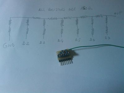
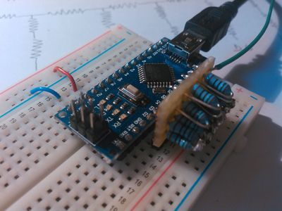
This is the schematics and the prototype...
It generates signals (very nice to 1300 hz, acceptable to 10khz) using a N - 2N resistor ladder DAC.
It has been designed to be plugged on 7 contiguous pins (GND, D2, ... , D7).
Using 150ohm resistors its internal resistance of 150ohm. It generates 0 to Vcc (actually 63/64 of Vcc) waves on an open circuit, 0 to Vcc/2 on a 150 ohm Load
The source code of the Arduino's sketch is:.
/* Arduino Direct Digital Synthresis (DSS) Signal generator */

/* Input:
 *  S10000 -> Sin wave ~100 hz
 *  T100000 -> Triangular ~1000 hz
 *  U5000 -> Rump UP ~50hz
 *  D20000 -> Rump DOWN ~200hz
 *  Q10000 -> Square 100hz
 *  %30 -> set the duty cycle to 30 % (for square waves only).
 */
uint8_t WAVE_MAP[4][128]= {{
  0x1F,0x21,0x22,0x24,0x25,0x27,0x28,0x2A,0x2B,0x2D,0x2E,0x30,0x31,0x32,0x33,0x35,
  0x36,0x37,0x38,0x39,0x3A,0x3A,0x3B,0x3C,0x3D,0x3D,0x3E,0x3E,0x3E,0x3F,0x3F,0x3F,
  0x3F,0x3F,0x3F,0x3F,0x3E,0x3E,0x3E,0x3D,0x3D,0x3C,0x3B,0x3A,0x3A,0x39,0x38,0x37,
  0x36,0x35,0x33,0x32,0x31,0x30,0x2E,0x2D,0x2B,0x2A,0x28,0x27,0x25,0x24,0x22,0x21,
  0x1F,0x1E,0x1C,0x1B,0x19,0x18,0x16,0x15,0x13,0x12,0x10,0x0F,0x0E,0x0C,0x0B,0x0A,
  0x09,0x08,0x07,0x06,0x05,0x04,0x03,0x03,0x02,0x01,0x01,0x00,0x00,0x00,0x00,0x00,
  0x00,0x00,0x00,0x00,0x00,0x00,0x01,0x01,0x02,0x03,0x03,0x04,0x05,0x06,0x07,0x08,
  0x09,0x0A,0x0B,0x0C,0x0E,0x0F,0x10,0x12,0x13,0x15,0x16,0x18,0x19,0x1B,0x1C,0x1E
  },{
  0x1F,0x20,0x21,0x22,0x23,0x24,0x25,0x26,0x27,0x28,0x29,0x2A,0x2B,0x2C,0x2D,0x2E,
  0x2F,0x30,0x31,0x32,0x33,0x34,0x35,0x36,0x37,0x38,0x39,0x3A,0x3B,0x3C,0x3D,0x3E,
  0x3F,0x3E,0x3D,0x3C,0x3B,0x3A,0x39,0x38,0x37,0x36,0x35,0x34,0x33,0x32,0x31,0x30,
  0x2F,0x2E,0x2D,0x2C,0x2B,0x2A,0x29,0x28,0x27,0x26,0x25,0x24,0x23,0x22,0x21,0x20,
  0x1F,0x1E,0x1D,0x1C,0x1B,0x1A,0x19,0x18,0x17,0x16,0x15,0x14,0x13,0x12,0x11,0x10,
  0x0F,0x0E,0x0D,0x0C,0x0B,0x0A,0x09,0x08,0x07,0x06,0x05,0x04,0x03,0x02,0x01,0x00,
  0x00,0x00,0x01,0x02,0x03,0x04,0x05,0x06,0x07,0x08,0x09,0x0A,0x0B,0x0C,0x0D,0x0E,
  0x0F,0x10,0x11,0x12,0x13,0x14,0x15,0x16,0x17,0x18,0x19,0x1A,0x1B,0x1C,0x1D,0x1E
  }, {
  0x00,0x00,0x00,0x01,0x01,0x02,0x02,0x03,0x03,0x04,0x04,0x05,0x05,0x06,0x06,0x07,
  0x07,0x08,0x08,0x09,0x09,0x0A,0x0A,0x0B,0x0B,0x0C,0x0C,0x0D,0x0D,0x0E,0x0E,0x0F,
  0x0F,0x10,0x10,0x11,0x11,0x12,0x12,0x13,0x13,0x14,0x14,0x15,0x15,0x16,0x16,0x17,
  0x17,0x18,0x18,0x19,0x19,0x1A,0x1A,0x1B,0x1B,0x1C,0x1C,0x1D,0x1D,0x1E,0x1E,0x1F,
  0x1F,0x20,0x20,0x21,0x21,0x22,0x22,0x23,0x23,0x24,0x24,0x25,0x25,0x26,0x26,0x27,
  0x27,0x28,0x28,0x29,0x29,0x2A,0x2A,0x2B,0x2B,0x2C,0x2C,0x2D,0x2D,0x2E,0x2E,0x2F,
  0x2F,0x30,0x30,0x31,0x31,0x32,0x32,0x33,0x33,0x34,0x34,0x35,0x35,0x36,0x36,0x37,
  0x37,0x38,0x38,0x39,0x39,0x3A,0x3A,0x3B,0x3B,0x3C,0x3C,0x3D,0x3D,0x3E,0x3E,0x3F
  }, {
  0x3F,0x3E,0x3E,0x3D,0x3D,0x3C,0x3C,0x3B,0x3B,0x3A,0x3A,0x39,0x39,0x38,0x38,0x37,
  0x37,0x36,0x36,0x35,0x35,0x34,0x34,0x33,0x33,0x32,0x32,0x31,0x31,0x30,0x30,0x2F,
  0x2F,0x2E,0x2E,0x2D,0x2D,0x2C,0x2C,0x2B,0x2B,0x2A,0x2A,0x29,0x29,0x28,0x28,0x27,
  0x27,0x26,0x26,0x25,0x25,0x24,0x24,0x23,0x23,0x22,0x22,0x21,0x21,0x20,0x20,0x1F,
  0x1F,0x1E,0x1E,0x1D,0x1D,0x1C,0x1C,0x1B,0x1B,0x1A,0x1A,0x19,0x19,0x18,0x18,0x17,
  0x17,0x16,0x16,0x15,0x15,0x14,0x14,0x13,0x13,0x12,0x12,0x11,0x11,0x10,0x10,0x0F,
  0x0F,0x0E,0x0E,0x0D,0x0D,0x0C,0x0C,0x0B,0x0B,0x0A,0x0A,0x09,0x09,0x08,0x08,0x07,
  0x07,0x06,0x06,0x05,0x05,0x04,0x04,0x03,0x03,0x02,0x02,0x01,0x01,0x00,0x00,0x00
}};

uint32_t phase_accumulator, phase_step;
uint8_t type;
uint8_t next_in = 0;
uint32_t step_in;
uint8_t DDS_OUT_MAP[128];
uint8_t  table_index;
uint8_t  duty_cycle = 50;

uint8_t create_out_map( void ){
  uint8_t i;
  if (type == 4) {
    uint8_t dmax = 128 * duty_cycle / 100;
    for (i=0;i<128;i++)
      DDS_OUT_MAP[i] = i < dmax ? 0xFC : 0;
  } else {
    for (i=0;i<128;i++)
      DDS_OUT_MAP[i] = WAVE_MAP[type][i] << 2;
  }
}

void setup() {
  pinMode(2, OUTPUT);
  pinMode(3, OUTPUT);
  pinMode(4, OUTPUT);
  pinMode(5, OUTPUT);
  pinMode(6, OUTPUT);
  pinMode(7, OUTPUT);
  Serial.begin(115200);
}

void serialEvent() {
  while(Serial.available()) {
    uint8_t inChar = Serial.read();
    //Serial.println(inChar);
    if (inChar == '\n' || inChar == '\r') {
      next_in = 0;
      if (type == 0xFF) {
        type = 4;
        duty_cycle = step_in;
        if (duty_cycle > 100) duty_cycle = 100;
        create_out_map();
        Serial.print("% ");
        Serial.println(duty_cycle);
      } else {
        create_out_map();
        phase_step = step_in;
        Serial.print(type);
        Serial.print(" ");
        Serial.println(phase_step);
      }
    } else if (next_in == 0) {
      type = 0;
      step_in = 0;
      if (inChar == 'T') type = 1;
      if (inChar == 'U') type = 2;
      if (inChar == 'D') type = 3;
      if (inChar == 'Q') type = 4;
      if (inChar == '%') type = 0xFF;
      next_in++;
    } else if (inChar >= '0' && inChar <= '9') {
      step_in = (step_in * 10) + (inChar - '0');
      next_in++;
    }
  }
}

void loop() {
  phase_accumulator=phase_accumulator + phase_step;
  table_index=(phase_accumulator)>>16;
  table_index=table_index>>1;
  PORTD = (PORTD & 0x3) | (DDS_OUT_MAP[table_index]);
}
Once the code has been loaded, open a serial terminal at 115200bps (e.g. the Arduino IDE's Serial Monitor or type 'screen /dev/ttyUSB0 115200').
Type:
- S10000 to generate a sinusoidal signal at 100hz
- T100000 triangular wave 1000hz
- U5000 ramp up at 50 hz
- D200000 ramp down at 2000hz
- Q1000 Square wave @ 10hz
- %30 change the duty cycle to 30% (only for square waves)
This prototype generates nice smooth signals up to 1300hz, the shape is still clear @ 10Khz, then the signal takes less and less sample per period... around 80Khz all signals are square waves.

