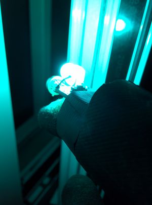
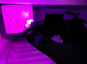
Arduino ir camera low cost
Qualche anno fa' avevo trovato questo progetto di termocamera ad infrarossi low cost sul sito PublicLab.
Mi ci ero imbattuto perche' una termocamera e' un oggetto affascinante ed anche molto utile per studiare dispersioni di calore negli edifici.
Per usarlo in modo scenografico ed avere una bella rappresentazione di una stanza l'idea è mettere un fotocamera reflex in posa manuale, con l'obiettivo aperto, in in una stanza buia e scansionare tutta la stanza per visualizzare punti caldi e freddi.
Ecco qui una galleria realizzata dagli ideatori del progetto.
Percio' avevo comprato il termometro ad infrarossi che poi e' rimasto nel cassetto per un po'. Ora che si riavvicina la stagione invernale ho pensato di realizzarlo praticamente, ma nel frattempo da quando il progetto e' stato realizzato e documentato le cose si sono evolute un pochino percio' ho fatto qualche modifica che presento qui.
Il sensore
MLX90614, prodotto da Melexis, e' un termometro a infrarossi I2C che non richiede il contatto con la superficie da misurare (attenzione va misurata la temperatura di una superficie, non e' possibile utilizzarlo per misurare la temperatura di gas o fiamme).
Questo sensore arriva a misurare fino a 360°C cosa che è molto interessante, inoltre fornisce misure accurate e può misurare oggetti anche relativamente lontani (ovviamente di dimensioni tai da rientrare nell'angolo di visione).
Va anche considerato che se si vuole misurare attraverso un vetro bisogna mettere a fuoco cio' che ci sta dietro, semplicemente appoggiando il termometro al vetro stesso altrimenti viene misurata la temperatura della prima superficie incontrata a distanza di fuoco.
I componenti del progetto:
- 1 Arduino mini
- 1 Covertitore USB/Seriale (opzionale, serve a leggere la temperatura precisa dal pc, ma non è indispensabile)
- 1 Sensore di temperatura ad infrarossi MLX90614
- 1 led RGB WS2812
- 1 guanto (opzionale)
- 1 batteria usb (consigliata)
Il codice
Rispetto al progetto originale ho modificato le soglie paer la tonalità del colore, ed aggiunto la gestione del led WS2812B che si pilota con un segnale digitale direttamente da arduino.
Rispetto all versione con led RGB classico non ho verificato lampeggio strani che mi lasciavano un pò perplesso.
// See http://bildr.org/2011/02/mlx90614-arduino/ for i2c library and instructions
// You must download the "twimaster.cpp" and "i2cmaster.h" files, and place them in a folder called "I2Cmaster".
// This must be placed in a folder called "libraries" which in turn should be placed in your Sketchbook folder (see Arduino's Preferences menu item to see where this is on your machine.).
// Typically, once you install these files, you must relaunch Arduino.

// Starting from original project of Public Lab
// The extra files are included in this Gist, as well as attached to the page http://publiclaboratory.org/tool/thermal-camera

// Modified to use WS2812B Led

#include <i2cmaster.h>
#include "Wire.h"
//#include "BlinkM_funcs.h"

#include <Adafruit_NeoPixel.h>
// Which pin on the Arduino is connected to the NeoPixels?
#define PIN           10
// How many NeoPixels are attached to the Arduino?
#define NUMPIXELS      1

Adafruit_NeoPixel pixels = Adafruit_NeoPixel(NUMPIXELS, PIN, NEO_GRB + NEO_KHZ400);

const float lowReading = 60;
const float highReading = 75;
const unsigned char separatorCharacter = 255;

void setup(){
	Serial.begin(9600);
	Serial.println("starting setup...");

	pixels.begin(); // This initializes the NeoPixel library.

	pinMode(9, INPUT);

	i2c_init(); //Initialise the i2c bus
	PORTC = (1 << PORTC4) | (1 << PORTC5);//enable pullups

	Serial.println("completed setup");

}

float normf(float x, float low, float high) {
	float y = (x - low) * 255.f / (high - low);
	if(y > 255) {
		y = 255;
	}
	if(y < 0) {
		y = 0;
	}
	return y;
}

void loop(){
	int dev = 0x5A<<1;
	int data_low = 0;
	int data_high = 0;
	int pec = 0;
        int x;

	i2c_start_wait(dev+I2C_WRITE);
	i2c_write(0x07);

	// read
	i2c_rep_start(dev+I2C_READ);
	data_low = i2c_readAck(); //Read 1 byte and then send ack
	data_high = i2c_readAck(); //Read 1 byte and then send ack
	pec = i2c_readNak();
	i2c_stop();

	//This converts high and low bytes together and processes temperature, MSB is a error bit and is ignored for temps
	double tempFactor = 0.02; // 0.02 degrees per LSB (measurement resolution of the MLX90614)
	double tempData = 0x0000; // zero out the data
	int frac; // data past the decimal point

	// This masks off the error bit of the high byte, then moves it left 8 bits and adds the low byte.
	tempData = (double)(((data_high & 0x007F) << 8) + data_low);
	tempData = (tempData * tempFactor)-0.01;
	float celsius = tempData - 273.15;
	float fahrenheit = (celsius*1.8) + 32;
	//Serial.println(fahrenheit);
	float state = normf(fahrenheit, lowReading, highReading);


	int hue = map(celsius,-15,50,15,315); // i primi due parametri indicano le temperatura minima e massima da misurare, i secondi il range di tonalità edl colore, per orientarsi http://hslpicker.com/
	setLedColorHSV(hue,1,1); //We are using Saturation and Value constant at 1
        Serial.print(state,2);
        Serial.print(" ");
	Serial.print(tempData);
	Serial.print(" gradi Kelvin, ");
	Serial.print(celsius);
	Serial.print(" gradi Celsius, ");
	Serial.print(330 - hue);
	Serial.println(" tonalita ");

}
//Convert a given HSV (Hue Saturation Value) to RGB(Red Green Blue) and set the led to the color
// h is hue value, integer between 0 and 360
// s is saturation value, double between 0 and 1
// v is value, double between 0 and 1
//http://splinter.com.au/blog/?p=29
void setLedColorHSV(int h, double s, double v) {
	//this is the algorithm to convert from RGB to HSV
	double r=0;
	double g=0;
	double b=0;

	double hf=h/60.0;

	int i=(int)floor(h/60.0);
	double f = h/60.0 - i;
	double pv = v * (1 - s);
	double qv = v * (1 - s*f);
	double tv = v * (1 - s * (1 - f));

	switch (i)
	{
		case 0: //rojo dominante
			r = v;
			g = tv;
			b = pv;
			break;
		case 1: //verde
			r = qv;
			g = v;
			b = pv;
			break;
		case 2:
			r = pv;
			g = v;
			b = tv;
			break;
		case 3: //azul
			r = pv;
			g = qv;
			b = v;
			break;
		case 4:
			r = tv;
			g = pv;
			b = v;
			break;
		case 5: //rojo
			r = v;
			g = pv;
			b = qv;
			break;
	}

	//set each component to a integer value between 0 and 255
	int red=constrain(255-(int)255*r,0,255);
	int green=constrain(255-(int)255*g,0,255);
	int blue=constrain(255-(int)255*b,0,255);

	setLedColor(red,green,blue);
}

//Sets the current color for the RGB LED
void setLedColor(int red, int green, int blue) {
	byte i = 0;                                             // posizione del led sul bus
	pixels.setPixelColor(i, pixels.Color(red,green,blue)); // Moderately bright green color.
	pixels.show();
}
Comunque il codice è salvato anche qui.

