Differenze tra le versioni di "Millefori: draw, print, mill and drill your experimental PCBs"
m (→millefori.py) |
m (→millefori.py) |
||
| Riga 90: | Riga 90: | ||
I am used to give the same track number in single-sided PCBs to tracks which will be connected through jumpers. In this way when moving the pointer over the PCB I can highlight all the cells electrically connected to the one currently pointed. | I am used to give the same track number in single-sided PCBs to tracks which will be connected through jumpers. In this way when moving the pointer over the PCB I can highlight all the cells electrically connected to the one currently pointed. | ||
| − | In two sided PCB, I decided to draw both sides as seen from the component side. The corresponding cells on both sides | + | In two sided PCB, I decided to draw both sides as seen from the component side. The corresponding cells on both sides belong to the same track if there is a hole. So drawing a new hole, drawing or modifying a track on a cell with a hole result in assigning the same track number on the corresponding cell on the other side. |
The track highlighting shows in light green the parts of the current track drawn on the other side. | The track highlighting shows in light green the parts of the current track drawn on the other side. | ||
Versione delle 10:07, 21 set 2014
This posting introduces millefori, a suite of programs to draw, print, mill and drill your experimental PCBs. The whole package is a 8K tgz file. Power of Python! Click HERE to download Millefori
I have used this program to create several single sided PCBs. The features to generate two-sided pcb have been added very recently to the code. I am still working on the machining procedures for two-sided PCBs.
Motivation
I used to create my experimental circuits on stripboards, (millefori in Italian). I created the tracks by soldering bare copper wires taken from recycled phone pairs.
Using my 3D printer as a CNC mill now I can mill my PCBs. There are several programs to manage electronics projects up to the design and production of the PCB like Geda or Kicad. None of them gives me the way to create circuits as I do by stripboards and wires.
By Geda or KiCAD, I need to draw the schematics, assign components' layouts, position the components on the pcb, draw the tracks (maybe following the suggestions). I can have a lot of features: 3D previews of the final product, auto check of the pcb-schematics consistency etc.
I am sure these are wonderful programs for large projects. But I want my millefori! A draft on the paper magically turned in a PCB.
So I wrote millefori. The software is a Beta or less, I have released it under a GPL2+ license.
Overview
The suite cosists of four programs:
- millefori.py is the interactive drawing program
- milleimg.py generates images of the PCBs (for documentation/printing)
- millegcode.py generates gcode to mill the pcb
- milledrill.py generates the gcode to drill the holes for the component pins.
millefori.py
Features:
- one-sided and two-sided PCB
- interactive drawing
- cut/copy/paste
- undo (currently 20 operations)
- json (readable) file format
- support for ~/.milleforirc
This is millefori's usage:
usage: millefori.py [-h] [--size SIZE] [--twosided] [--noxflip] [--xyflip]
                    [--centered]
                    PATH

Drawing program for simple PCBs.

positional arguments:
  PATH                  pathname

optional arguments:
  -h, --help            show this help message and exit
  --size SIZE, -s SIZE  size (in mm) default:120x100
  --twosided, -2        two sided PCB
  --noxflip             backside: do not flip x coords
  --xyflip              backside: flip x and y
  --centered            xy centered
It needs a path. If the file does not exist, millefori creates a new pcb otherwise it loads the file. --size and --twosided are meaningful for new files, otherwise the size and the number of size are retrieved from the loaded file.
--noxflip --xyflip --centered are for twosided PCBs: millefori displays the final X,Y coordinates in mm of the current position of the mouse when the circuit will be milled. Clearly these coordinates depend upon some choices on the production process. Millefori suite supports two different ways to mill the reverse side (component side) of the pcb: xflip and xyflip:
- xflip: turn the board along the y axis, as if it were a printed page and you want to read the back side (default)
- xyflip: flip the board along the bisector of the first quadrant.
xflip can have alignment problems if the board is not exacly as large as expected. xyflip requires a good alignment and a correct positioning of the origin. For xyflip two alignment keys (two small nails fixing the board on the working surface) positioned on the bisector guarantee that the two sides of the PCB are correctly aligned. -- centered: standard board sizes are in mm, tracks in tenth of inches. The remainder (less of 0.1") can be left on the side opposite to the origin or equally distributed on both sides.
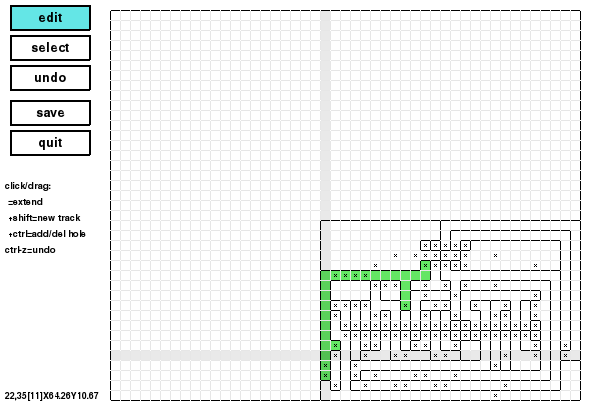
This is Millefori's interface for one-sided PCBs:
This is the edit mode. Moving the pointer on the image, the entire track below the pointer is higlighted in green. A slightly darker x/y cross helps for alignments. As the help message below the buttons says, it is possible to extend a track just by clicking on it and dragging the pointer up to the desidered position. It the user pushes the shift key before clicking a cell of the pcb, a new track is created. Ctrl creates or deletes drilled holes. Ctrl-clicking a cell where there is not a hole (depicted as a small x), the hole is added. Viceversa, if there was already a hole, ctrl-click deletes the hole. It is possible to drag this operation to create rows of holes (for pin-strips, or IC rows of pins).
On the lowest left corner, millefori displays the current position. For example, in the snapshot above:
22,35[11] X64.26 Y10.67
means that the current cell is the 22nd left to right and the 35th from the top. The number enclosed in square brackets is the track number. Millefori basic idea is that contiguous cells belonging to different tracks must be separated by milling away the copper on the boundary segment between them. X and Y are the CNC coordinates. Please note that the CNC origin is on the lowest right corner. The Y axis is naturally reversed between screen and CNC coordinates. Moreover, millefori has been designed to draw the circuit's tracks from the component side. The CNC has to print the soldering side, so it must be reflected left-to-right.
There are some "hidden" functions (I have not added them to the help message below the buttons). ctrl-2/ctrl-1: convert single-sided PCBs in twosided and viceversa. By clicking and dragging using the third/right button if the mouse, it gives the same number to the tracks at the enpoints of the operation. I am used to give the same track number in single-sided PCBs to tracks which will be connected through jumpers. In this way when moving the pointer over the PCB I can highlight all the cells electrically connected to the one currently pointed.
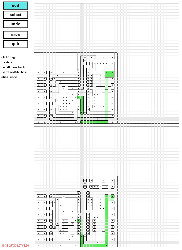
In two sided PCB, I decided to draw both sides as seen from the component side. The corresponding cells on both sides belong to the same track if there is a hole. So drawing a new hole, drawing or modifying a track on a cell with a hole result in assigning the same track number on the corresponding cell on the other side.
The track highlighting shows in light green the parts of the current track drawn on the other side. The current position is in black when it refers to the soldering side, in red when it shows the coordinates on the component side. The XY cross has two horizontal lines to show the current position on both sides.
milleimg.py
Milleimg converts a PCB side to an image file. Use this tool to print a PCB on paper or publish its image on a web site.
Here is the usage:
usage: milleimg.py [-h] [-r] [-2] input_file output_file

positional arguments:
  input_file      millefori input file
  output_file     output file (.png, .pdf ...)

optional arguments:
  -h, --help      show this help message and exit
  -r, --reverse   soldering side (CNC working side for front)
  -2, --backside  backside (component side)
Milleimg uses the Python Imaging Library (PIL). The output format depends upon the output file suffix. PIL supports very many file formats. Among the others: gif, png, jpg, pdf, eps, tiff.
millegcode.py
This program generates the g-code to mill the tracks on a copper plated board.
usage: millegcode.py [-h] [-u UPLEVEL] [-d DOWNLEVEL] [-z ZSPEED]
                     [--g0speed G0SPEED] [--g1speed G1SPEED] [-v] [-1] [-2]
                     [--xyflip] [--centered]
                     input_file

positional arguments:
  input_file            millefori input file

optional arguments:
  -h, --help            show this help message and exit
  -u UPLEVEL, --uplevel UPLEVEL
                        traveling z-level (2.0)
  -d DOWNLEVEL, --downlevel DOWNLEVEL
                        milling z-level (-0.1)
  -z ZSPEED, --zspeed ZSPEED
                        drilling z speed (50)
  --g0speed G0SPEED     moving speed (2000)
  --g1speed G1SPEED     working speed (100)
  -v, --verbose         verbose output (add comments)
  -1, --no1             skip track 1
  -2, --backside        backside (component side)
  --xyflip              backside: flip x and y, implies -2
  --centered            xy centered
Millegcode creates its output on the standard output, redirect it on a file if you want. -u, -d, -z, --g0speed --g1speed are parameters for the CNC. -u and -d define the z-axis positions to move the tool and to mill the tracks. The uplevel value must be just above the surface and the downlevel should permit to remove the copper layer completely. For a good result double check that the board is perfectly horizontal. The default values are 2mm for up and 0.1mm for down. The z value of the surface should be 0 for all x,y otherwise your PCB can have deep cuts between tracks on one side and the copper just scraped on the other.
zspeed is the speed used to move the tool up and down, g0speed is the speed to position the tool (at z uplevel) for the next track. g1speed is a critical value: this is the machining speed, i.e. the x,y moving speed of the tool during the milling operation. High values can damage the milling tip, give a worse result and generate high traversal forces which can stress the stepper motors and move the board if the fixation points to the CNC are not strong enough. Low values are safer but increase the time needed to have your board completed.
-v adds comments to the g-code. This is useful if you want to see each track on millefori's graphical interface. Sometimes, when a track has not been milled perfectly I select just its section on the gcode and send it again to the PCB (maybe lowering a bit the z=0 level). Double check to have the final "G1 Z2.0 F50" g-code instruction in your file! Some machines and some g-code sending programs (like repetier host) are used to moving the tool in a pre-defined xy position at the end, If you forget to muve your tool above the working level you can damage both the board and the milling tip.
By -1 you ask millegcode to skip milling the track #1. For mollefori track #1 includes the parts of the board where you have not drawn any track. In other word it is the complementary set of your circuit. I use -1 to recycle my boards. I mill a circuit on one corner (usally the lower left) and I cut it off from the board. I can later use the reamining part of the board to mill another PCB. Without -1 the g-code mills the logical boundary of the whole board so there is a cut all around as the size of the circuit is a bit smaller than the board (for the board size-multiple of inch/10 difference).
The g-code of the soldering side is x-mirrored with respect to its appearance on millefori's GUI.
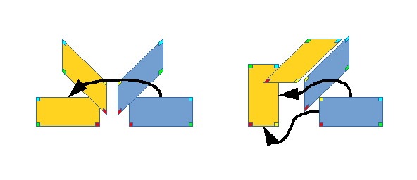
-2 and --xyflip are the options to mill the back/component side of a two sided PCB. Use -2 if you want to flip your board left to right, --xyflip if you want to flip it around the xy bisector.
The picture on the left here above shows how to flip the board for -2, on the right the rotation for -xyflip. The colored square at corners show the corresponding vertices on both sides.
milledrill.py
I use this program with a 0.9mm drilling tip to create the holes for the component terminals.
usage: milledrill.py [-h] [-u UPLEVEL] [-d DRILLLEVEL] [-z ZSPEED]
                     [--g0speed G0SPEED] [--g1speed G1SPEED] [-v] [--centered]
                     input_file

positional arguments:
  input_file            millefori input file

optional arguments:
  -h, --help            show this help message and exit
  -u UPLEVEL, --uplevel UPLEVEL
                        traveling z-level (2.0)
  -d DRILLLEVEL, --drilllevel DRILLLEVEL
                        drill down to this z-level (-2.2)
  -z ZSPEED, --zspeed ZSPEED
                        drilling z speed (50)
  --g0speed G0SPEED     moving speed (2000)
  --g1speed G1SPEED     working speed (100)
  -v, --verbose         verbose output (add comments)
  --centered            xy centered
all the arguments are the same as in millegcode but -d/--drilllevel. This is the z value to drill the board up to the reverse side. I use a wooden working surface under the board to protect the CNC platform.
.milleforirc
It is possible to create a .milleforirc file in your home directory. It is a json file, here is mine:
{
  "uplevel": 2.0,
  "downlevel": -0.1,
  "drilllevel": -2.2
}
This file defines the default values for all the numerical parameters permitted of the command line for millefori, millegcode and milledrill: uplevel, downlevel, zspeed, drilllevel, size.


