Millefori: draw, print, mill and drill your experimental PCBs
This posting introduces millefori, a suite of programs to draw, print, mill and drill your experimental PCBs. The whole package is a 8K tgz file. Power of Python!
Motivation
I used to create my experimental circuits on stripboards, (millefori in Italian). I created the tracks by soldering bare copper wires taken from recycled phone pairs.
Using my 3D printer as a CNC now I can mill my PCBs. There are several programs to manage electronics projects up to the design and production of the PCB like Geda or Kicad. None of them gives me the way to create circuits as I do by stripboards and wires.
I need to draw the schematics, assign components' layouts, position the components on the pcb, draw the tracks (maybe following the suggestions). I can have a lot of features: 3D previews of the final product, auto check of the pcb-schematics consistency etc.
I am sure these are wonderful programs for large projects. I want my millefori!
So I wrote millefori. The software is a Beta or less, I have released it under a GPL2+ license.
Overview
The suite cosists of four programs:
- millefori.py is the interactive drawing program
- milleimg.py generates images of the PCBs (for documentation/printing)
- millegcode.py generates gcode to mill the pcb
- milledrill.py generates the gcode to drill the holes for the component pins.
millefori.py
Features:
- one-sided and two-sided PCB
- interactive drawing
- cut/copy/paste
- undo (currently 20 operations)
- json (readable) file format
- support for ~/.milleforirc
This is millefori's usage:
usage: millefori.py [-h] [--size SIZE] [--twosided] [--noxflip] [--xyflip]
                    [--centered]
                    PATH

Drawing program for simple PCBs.

positional arguments:
  PATH                  pathname

optional arguments:
  -h, --help            show this help message and exit
  --size SIZE, -s SIZE  size (in mm) default:120x100
  --twosided, -2        two sided PCB
  --noxflip             backside: do not flip x coords
  --xyflip              backside: flip x and y
  --centered            xy centered
It needs a path. If the file does not exist, millefori creates a new pcb otherwise it loads the file. --size and --twosided are meaningful for new files, otherwise the size and the number of size are retrieved from the loaded file.
--noxflip --xyflip --centered are for twosided PCBs: millefori displays the final X,Y coordinates in mm of the current position of the mouse when the circuit will be milled. Clearly these coordinates depend upon some choices on the production process. Millefori suite supports two different ways to mill the reverse side (component side) of the pcb: xflip and xyflip:
- xflip: turn the board along the y axis, as if it were a printed page and you want to read the back side (default)
- xyflip: flip the board along the bisector of the first quadrant.
xflip can have alignment problems if the board is not exacly as large as expected. xyflip requires a good alignment and a correct positioning of the origin. For xyflip two alignment keys (two small nails fixing the board on the working surface) positioned on the bisector guarantee that the two sides of the PCB are correctly aligned. -- centered: standard board sizes are in mm, tracks in tenth of inches. The remainder (less of 0.1") can be left on the side opposite to the origin or equally distributed on both sides.
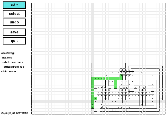
This is Millefori's interface for one-sided PCBs:
This is the edit mode. Moving the pointer on the image, the entire track below the pointer is higlighted in green. A slightly darker x/y cross helps for alignments. As the help message below the button says, it is possible to extend a track just by clicking on it and dragging the pointer up to the desidered position. It the user pushes the shift key before clicking a cell of the pcb, a new track is created. Ctrl creates or deletes drilled holes. Ctrl-clicking a cell where there is not a hole (depicted as a small x), the hole is added. Viceversa, if there was already a hole, ctrl-click deletes the hole. It is possible to drag this operation to create rows of holes (for pin-strips, or IC rows of pins).
On the lowest left corner, millefori displays the current position. For example, in the snapshot above:
22,35[11] X64.26 Y10.67
means that on the cell is the 22nd left to right and the 35th from the top. The number enclosed in square brackets is the track number. Millefori basic idea is that contiguous cells belonging to different tracks must be separated by milling away the copper on the boundary segment between them. X and Y are the CNC coordinates. Please note that the CNC origin is on the lowest right corner. The Y axis is naturally reversed between screen and CNC coordinates. Moreover, millefori has been designed to draw the circuit's tracks from the component side. The CNC has to print the soldering side, so it must be reflected left-to-right.
There are some "hidden" functions (I have not added them to the help message below the buttons). ctrl-2/ctrl-1: convert single-sided PCBs in twosided and viceversa. clicking and dragging using the third/right button if the mouse, gives the same number to the tracks at the enpoints of the operation.
