No more secrets Part 6: Let us play together
The circuits presented in the previous sections can be implemented on a single breadboard. In this section we will see how to connect several breadboards together to build larger, more complex circuits.
If you have two bradboard, or you meet a friend of yours who likes this booklet and has another breadboard, it is possible to build a complete two control bit demux.
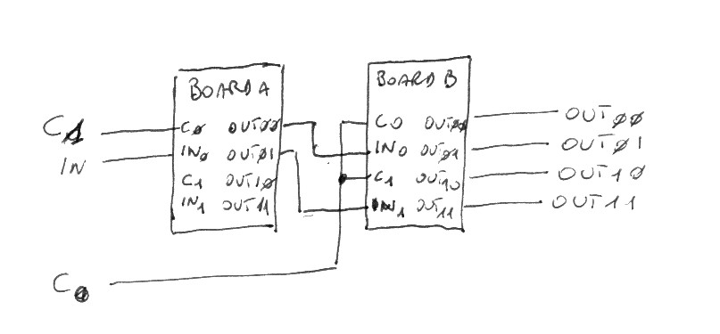
Build the two demux circuit illustrated in the previous section on both breadboards and then connect them together as illustrated here below.
Only one of the demux(es) in boardA is actually used. When both c0 and c1 have value 0 then in is copied to out00, and so on as it is summarized in the following table:
c1 c0
 0  0  in is copied to out00
 0  1  in is copied to out01
 1  0  in is copied to out10
 1  1  in is copied to out11
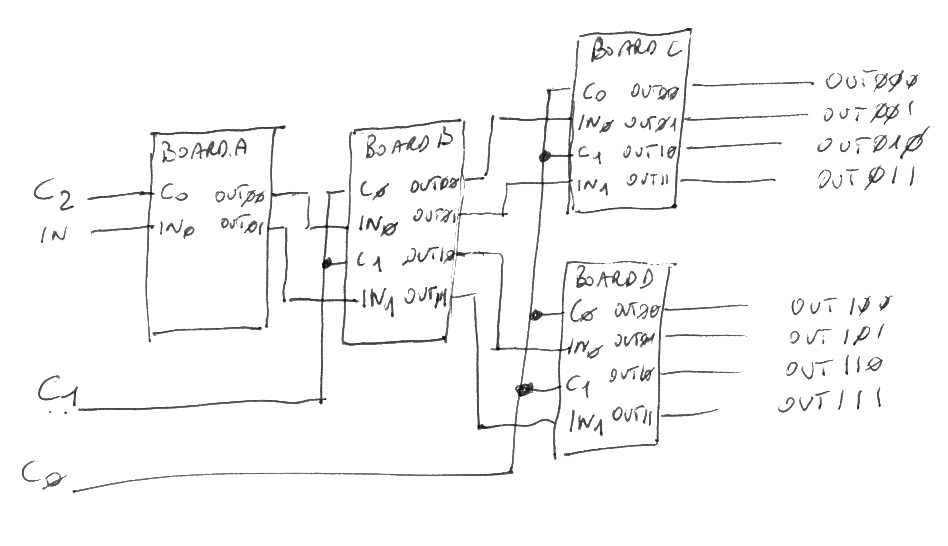
To build a three control bit demux (eight output lines) more breadboards (or more friends) are needed. The following picture shows how four breadboards all set up as two demux circuits (as seen in the previous chapter) can be connected to form a three control bit demux.
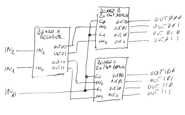
Three breadboards can be used to build a three control bit decoder. The first board must be configured as a twi bit decoder and both the others as demux (2x1bit demux). All you need is then to connect the boards as follows:
in0 in1 in2 Enabled output
 0   0   0  out00 muxA
 0   0   1  out01 muxA
 0   1   0  out10 muxA
 0   1   1  out11 muxA
 1   0   0  out00 muxB
 1   0   1  out01 muxB
 1   1   0  out10 muxB
 1   1   1  out11 muxB
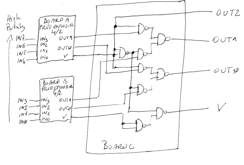
An eight input/three output lines priority encoder requires three breadboards, two of them configured as four inputs/2 outputs priority encoders while the third needs a custom circuit to combine the partial results.
The V output bit of the highest 4/2 prio encoder is the new most significant bit of the output. This v bit drives two 1-bit mutexes. When V of the highest priority encoder, its out1 and out0 output are copied to the global out1 and out0 results. If V is false, the output value of the lowest priority encored are copied instead. The global V (valid) bit output is one when at least one V bit of the 2 bit encoders is one, in fact it is the result of an OR gate.
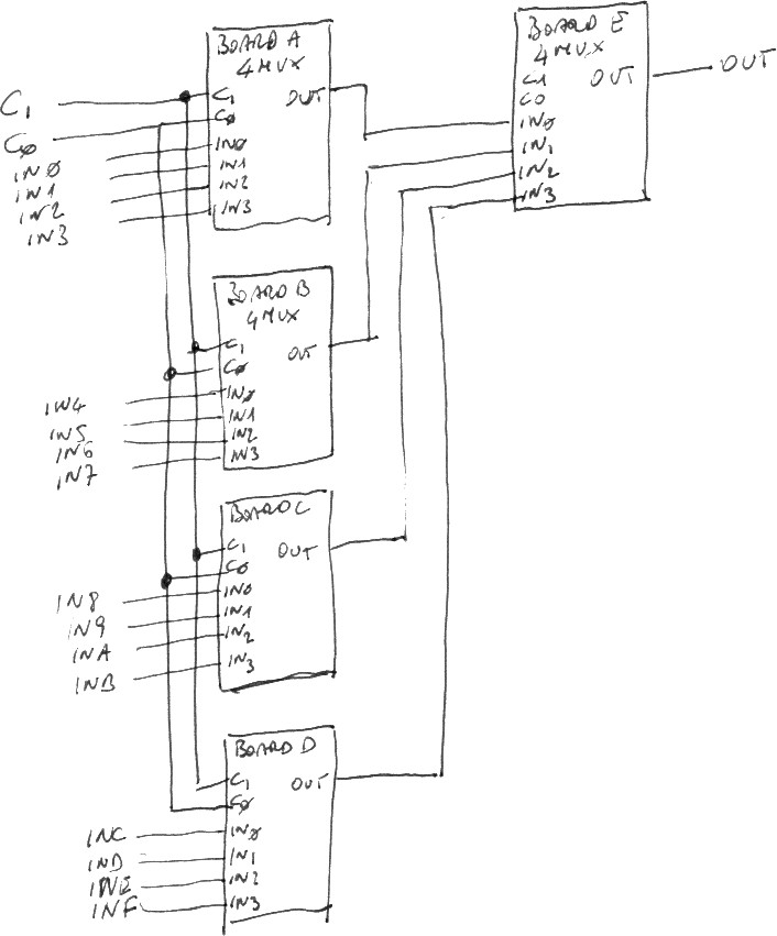
If you have many boards (or many friends), it is possible to build a sixteen data/four control bit multiplex using five breadboard, all set up as four inputs/two control bits boards. The following schematics shows how to connect the boards:
