Differenze tra le versioni di "No more secrets in your CPU: Part 1"
m |
m |
||
| Riga 34: | Riga 34: | ||
[[File:transistorfinger.png]] | [[File:transistorfinger.png]] | ||
| + | |||
| + | Let us consider this circuit: | ||
| + | |||
| + | [[File:led.png]] | ||
| + | |||
| + | The current flows through the resistor and the led diode which turns on. | ||
| + | The resistor in this circuit limits the current so that the diode cannot be | ||
| + | damaged. | ||
| + | |||
| + | Let us add a button to the previous circuit in this way: | ||
| + | |||
| + | [[File:lednot.png]] | ||
| + | |||
| + | If you push the button, the current flows through the button where the | ||
| + | resistence is null instead of passing through the diode. As a consequence, | ||
| + | the led turns off. | ||
| + | If we use two buttons connected as depicted here below (in series), the led | ||
| + | diode turns off when both buttons get pushed. | ||
| + | |||
| + | [[File:nednand.png]] | ||
| + | |||
| + | We have said that a transistor may work as a remotely controlled finger | ||
| + | which pushes a button, so we can redesign the circuits about using | ||
| + | transistors in lieu of buttons. | ||
| + | |||
| + | As we will see almost all the components of a CPU (a processor) can be | ||
| + | built using a large number of these circuits. More precisely the circuit | ||
| + | using two transistors is a basic brick that can can be used to build all the | ||
| + | others. | ||
| + | |||
| + | [[File:tnotnand.png]] | ||
| + | |||
| + | The circuit on the left, having one input and one transistor, is a NOT | ||
| + | gate. It negates its input: when its input is connected to the positive pin | ||
| + | of the power supply (+ 5V) the output is 0V. If there is a led connected it | ||
| + | is off. Viceversa if the input is connected to the negative pin (0V), or | ||
| + | left not connected, the output is 5V, the led is on. We will call 0V as | ||
| + | the logical state 0 and the logical state 1 is +5V. | ||
| + | |||
| + | The logical table of a NOT gate is: | ||
| + | IN OUT | ||
| + | 0 1 | ||
| + | 1 0 | ||
| + | |||
| + | The second circuit is a Not AND, usually abbreviated as NAND. | ||
| + | Its logical table is: | ||
| + | IN1 IN2 OUT | ||
| + | 0 0 1 | ||
| + | 0 1 1 | ||
| + | 1 0 1 | ||
| + | 1 1 0 | ||
Versione delle 12:12, 14 mag 2014
This is the first of a set of postings. I am writing here, on my BLiki, the draft of a booklet about Computer Architecture in the spirit of "Making".
This booklet describes an educational tool created to reveal the secrets of the basic elements of digital computers. Nothing magic happens in the processor of you computers, it is just a matter of circuits an commutation of electric currents. Everything works using an elementary switching device: the transistor.
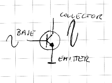
A transistor is an electronic component which is able to drive a high current on the basis of a low control current. It is basically an amplifier. The control pin is the base (B), the reference gate is the emitter(E), the output gate is the collector(C).
The low control current flowing between the base and the emitter, enables a high current between the collector and the emitter. For NPN transistors, the ones we use, these currents are positive (the potential, or voltage of the Base and Collector is higher than the potential of the Emitter). The symbol of a NPN transistor has the arrow of the emitter pointing outwards. There are other transistors named PNP, having the inwards arrow in their symbol. PNP transistors use negative currents instead of positive currents.
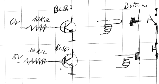
For our purposes we will use our transistors as binary switches. In fact a current of 0.5mA (almost) saturate a transistor of the type used in our experiemental tool (BC547). A transistor behaves like a remotely controlled finger pushing a button. When a current flows through the transistor's base the finger pushes the button, otherwise it keeps it released.
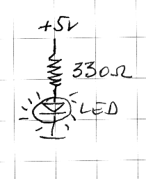
Let us consider this circuit:
The current flows through the resistor and the led diode which turns on. The resistor in this circuit limits the current so that the diode cannot be damaged.
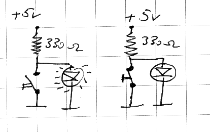
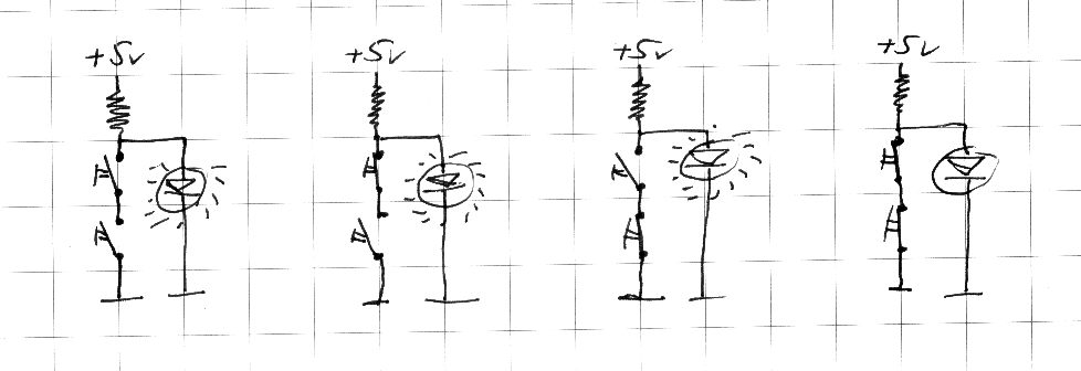
Let us add a button to the previous circuit in this way:
If you push the button, the current flows through the button where the resistence is null instead of passing through the diode. As a consequence, the led turns off. If we use two buttons connected as depicted here below (in series), the led diode turns off when both buttons get pushed.
We have said that a transistor may work as a remotely controlled finger which pushes a button, so we can redesign the circuits about using transistors in lieu of buttons.
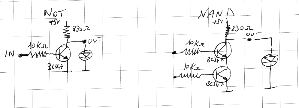
As we will see almost all the components of a CPU (a processor) can be built using a large number of these circuits. More precisely the circuit using two transistors is a basic brick that can can be used to build all the others.
The circuit on the left, having one input and one transistor, is a NOT gate. It negates its input: when its input is connected to the positive pin of the power supply (+ 5V) the output is 0V. If there is a led connected it is off. Viceversa if the input is connected to the negative pin (0V), or left not connected, the output is 5V, the led is on. We will call 0V as the logical state 0 and the logical state 1 is +5V.
The logical table of a NOT gate is:
 IN OUT
 0  1
 1  0
The second circuit is a Not AND, usually abbreviated as NAND. Its logical table is:
 IN1 IN2 OUT
 0   0   1
 0   1   1
 1   0   1
 1   1   0
