Differenze tra le versioni di "Some experiments on Radio Remote Controls"
Jump to navigation
Jump to search
| Riga 16: | Riga 16: | ||
There is already a library named RC-Switch. It can be downloaded from github. | There is already a library named RC-Switch. It can be downloaded from github. | ||
This is its latest release: [https://github.com/sui77/rc-switch/releases/tag/v2.52 https://github.com/sui77/rc-switch/releases/tag/v2.52]. | This is its latest release: [https://github.com/sui77/rc-switch/releases/tag/v2.52 https://github.com/sui77/rc-switch/releases/tag/v2.52]. | ||
| + | |||
| + | The library includes a set a of examples. I have created a specific sketch for my avidsen set. | ||
| + | |||
| + | The wiring between the Arduino and TX/RX modules is: | ||
| + | <pre> | ||
| + | TX has three pins | ||
| + | (left to right watching the component side of the PCB, there are clear labels): | ||
| + | DATA <-> Arduino GPIO 2 | ||
| + | Vcc <-> Arduino 5v | ||
| + | GND <-> Arduino GND | ||
| + | |||
| + | RX has four pins | ||
| + | (left to right watching the component side of the PCB, the labels are printer on the reverse side of the PCB) | ||
| + | Vcc <-> Arduino 5v | ||
| + | DATA <-> Arduino GPIO 10 | ||
| + | DATA <-> (the two DATA pins are connected together, so either can be used). | ||
| + | GND <-> Arduino GND | ||
| + | </pre> | ||
| + | |||
| + | <source lang=c> | ||
| + | #include <RCSwitch.h> | ||
| + | |||
| + | RCSwitch mySwitch = RCSwitch(); | ||
| + | |||
| + | #define BINARY 0 | ||
| + | #define SWITCH 1 | ||
| + | int mode=SWITCH; | ||
| + | |||
| + | void setup() { | ||
| + | Serial.begin(115200); | ||
| + | mySwitch.enableReceive(0); // Receiver on inerrupt 0 => that is pin #2 | ||
| + | mySwitch.enableTransmit(10); | ||
| + | } | ||
| + | |||
| + | void incodeProcess(unsigned long code) { | ||
| + | static char outbuf[25]; | ||
| + | int i; | ||
| + | switch (mode) { | ||
| + | case BINARY: | ||
| + | for (i=0; i<24; i++, code>>=1) | ||
| + | outbuf[23-i] = (code & 1) ? '1' : '0'; | ||
| + | break; | ||
| + | case SWITCH: | ||
| + | outbuf[5]=outbuf[11]=' '; | ||
| + | outbuf[13]=0; | ||
| + | switch (code & 0xF) { | ||
| + | case 0x1: outbuf[12]='1';break; | ||
| + | case 0x4: outbuf[12]='0';break; | ||
| + | default: return; | ||
| + | } | ||
| + | code>>=4; | ||
| + | for (i=0; i<5; i++, code>>=2) | ||
| + | outbuf[10-i] = (code & 1) ? '0' : '1'; | ||
| + | for (i=0; i<5; i++, code>>=2) | ||
| + | outbuf[4-i] = (code & 1) ? '0' : '1'; | ||
| + | break; | ||
| + | } | ||
| + | Serial.print(outbuf); | ||
| + | Serial.println(); | ||
| + | } | ||
| + | |||
| + | void inlineProcess(char *line) { | ||
| + | if (line[5] == ' ' && line[11] == ' ' && line[13] == 0) { | ||
| + | line[5] = line[11] = 0; | ||
| + | switch (line[12]) { | ||
| + | case '1': | ||
| + | mySwitch.switchOn(line,line+6); | ||
| + | break; | ||
| + | case '0': | ||
| + | mySwitch.switchOff(line,line+6); | ||
| + | break; | ||
| + | default: | ||
| + | return; | ||
| + | } | ||
| + | } else | ||
| + | mySwitch.send(line); | ||
| + | } | ||
| + | |||
| + | void inbyte(int inchar) { | ||
| + | static char inbuf[64]; | ||
| + | static int pos=0; | ||
| + | if (inchar == '\r' || pos == 64) { | ||
| + | inbuf[pos]=0; | ||
| + | inlineProcess(inbuf); | ||
| + | pos=0; | ||
| + | } else if (inchar < ' ') { | ||
| + | switch (inchar) { | ||
| + | case 0x2: //ctrl-b | ||
| + | mode=BINARY; | ||
| + | break; | ||
| + | case 0x17: //ctrl-W | ||
| + | mode=SWITCH; | ||
| + | break; | ||
| + | } | ||
| + | } else | ||
| + | inbuf[pos++]=inchar; | ||
| + | } | ||
| + | |||
| + | void loop() { | ||
| + | if (mySwitch.available()) { | ||
| + | incodeProcess(mySwitch.getReceivedValue()); | ||
| + | mySwitch.resetAvailable(); | ||
| + | } | ||
| + | while (Serial.available()) { | ||
| + | inbyte(Serial.read()); | ||
| + | } | ||
| + | } | ||
| + | </source> | ||
Versione delle 16:12, 4 giu 2016
Arduino and Radio Controller Sockets
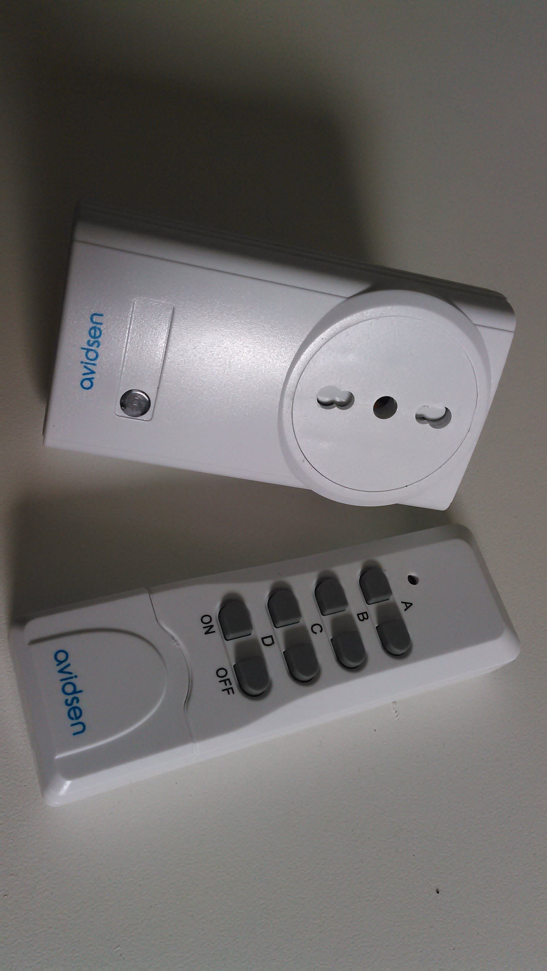
I have bought a kit by avidsen including a socket and a remote.
My goal was twice. I wanted to control avidsen sockets using an arduino and to get commands from a avidsen remote.
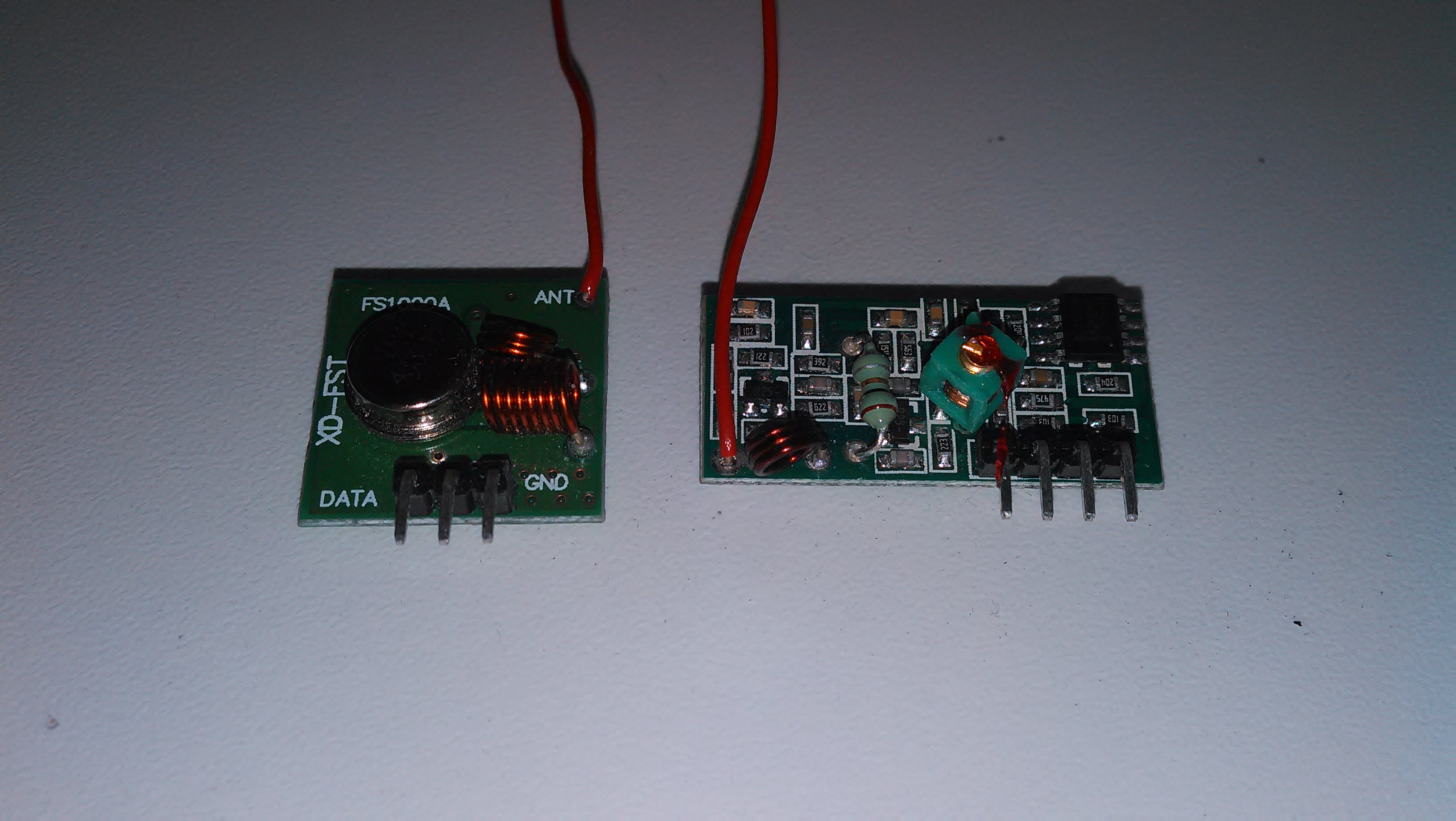
For that I have taken a set of RX and TX 433.92Mhz modules. This kind of modules are very common on e-bay.
They are usually provided without an antenna: they need a 17.3 cm wire soldered to the ANT labelled terminal.
There is already a library named RC-Switch. It can be downloaded from github. This is its latest release: https://github.com/sui77/rc-switch/releases/tag/v2.52.
The library includes a set a of examples. I have created a specific sketch for my avidsen set.
The wiring between the Arduino and TX/RX modules is:
TX has three pins
(left to right watching the component side of the PCB, there are clear labels):
   DATA <-> Arduino GPIO 2
   Vcc  <-> Arduino 5v
   GND  <-> Arduino GND

RX has four pins
(left to right watching the component side of the PCB, the labels are printer on the reverse side of the PCB)
   Vcc  <-> Arduino 5v
   DATA <-> Arduino GPIO 10
   DATA <-> (the two DATA pins are connected together, so either can be used).
   GND  <-> Arduino GND
#include <RCSwitch.h>

RCSwitch mySwitch = RCSwitch();

#define BINARY 0
#define SWITCH 1
int mode=SWITCH;

void setup() {
  Serial.begin(115200);
  mySwitch.enableReceive(0);  // Receiver on inerrupt 0 => that is pin #2
  mySwitch.enableTransmit(10);
}

void incodeProcess(unsigned long code) {
	static char outbuf[25];
	int i;
	switch (mode) {
		case BINARY:
			for (i=0; i<24; i++, code>>=1)
				outbuf[23-i] = (code & 1) ? '1' : '0';
			break;
		case SWITCH:
			outbuf[5]=outbuf[11]=' ';
			outbuf[13]=0;
			switch (code & 0xF) {
				case 0x1: outbuf[12]='1';break;
				case 0x4: outbuf[12]='0';break;
				default: return;
			}
			code>>=4;
			for (i=0; i<5; i++, code>>=2)
				outbuf[10-i] = (code & 1) ? '0' : '1';
			for (i=0; i<5; i++, code>>=2)
				outbuf[4-i] = (code & 1) ? '0' : '1';
			break;
	}
	Serial.print(outbuf);
	Serial.println();
}

void inlineProcess(char *line) {
	if (line[5] == ' ' && line[11] == ' ' && line[13] == 0) {
		line[5] = line[11] = 0;
		switch (line[12]) {
			case '1':
				mySwitch.switchOn(line,line+6);
				break;
			case '0':
				mySwitch.switchOff(line,line+6);
				break;
			default:
				return;
		}
	} else
		mySwitch.send(line);
}

void inbyte(int inchar) {
	static char inbuf[64];
	static int pos=0;
	if (inchar == '\r' || pos == 64) {
		inbuf[pos]=0;
		inlineProcess(inbuf);
		pos=0;
	} else if (inchar < ' ') {
		switch (inchar) {
			case 0x2: //ctrl-b
				mode=BINARY;
				break;
			case 0x17: //ctrl-W
				mode=SWITCH;
				break;
		}
	} else
		inbuf[pos++]=inchar;
}

void loop() {
  if (mySwitch.available()) {
		incodeProcess(mySwitch.getReceivedValue());
		mySwitch.resetAvailable();
	}
	while (Serial.available()) {
		inbyte(Serial.read());
	}
}

