Some experiments on Radio Remote Controls
Arduino and Radio Controller Sockets
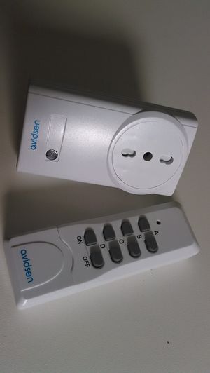
I have bought a kit by avidsen including a socket and a remote.
My goal was twice. I wanted to control avidsen sockets using an arduino and to get commands from a avidsen remote.
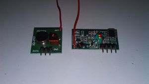
For that I have taken a set of RX and TX 433.92Mhz modules. This kind of modules are very common on e-bay.
They are usually provided without an antenna: they need a 17.3 cm wire soldered to the ANT labelled terminal.
There is already a library named RC-Switch. It can be downloaded from github. This is its latest release: https://github.com/sui77/rc-switch/releases/tag/v2.52.
The library includes a set a of examples. I have created a specific sketch for my avidsen set.
The wiring between the Arduino and TX/RX modules is:
TX has three pins
(left to right watching the component side of the PCB, there are clear labels):
   DATA <-> Arduino GPIO 2
   Vcc  <-> Arduino 5v
   GND  <-> Arduino GND

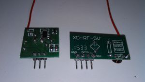
RX has four pins
(left to right watching the component side of the PCB, the labels are printed on the reverse side of the PCB)
   Vcc  <-> Arduino 5v
   DATA <-> Arduino GPIO 10
   DATA <-> (the two DATA pins are connected together, so either can be used).
   GND  <-> Arduino GND
#include <RCSwitch.h>

RCSwitch mySwitch = RCSwitch();

#define BINARY 0
#define SWITCH 1
int mode=SWITCH;

void setup() {
  Serial.begin(115200);
  mySwitch.enableReceive(0);  // Receiver on inerrupt 0 => that is pin #2
  mySwitch.enableTransmit(10);
}

void incodeProcess(unsigned long code) {
	static char outbuf[25];
	int i;
	switch (mode) {
		case BINARY:
			for (i=0; i<24; i++, code>>=1)
				outbuf[23-i] = (code & 1) ? '1' : '0';
			break;
		case SWITCH:
			outbuf[5]=outbuf[11]=' ';
			outbuf[13]=0;
			switch (code & 0xF) {
				case 0x1: outbuf[12]='1';break;
				case 0x4: outbuf[12]='0';break;
				default: return;
			}
			code>>=4;
			for (i=0; i<5; i++, code>>=2)
				outbuf[10-i] = (code & 1) ? '0' : '1';
			for (i=0; i<5; i++, code>>=2)
				outbuf[4-i] = (code & 1) ? '0' : '1';
			break;
	}
	Serial.print(outbuf);
	Serial.println();
}

void inlineProcess(char *line) {
	if (line[5] == ' ' && line[11] == ' ' && line[13] == 0) {
		line[5] = line[11] = 0;
		switch (line[12]) {
			case '1':
				mySwitch.switchOn(line,line+6);
				break;
			case '0':
				mySwitch.switchOff(line,line+6);
				break;
			default:
				return;
		}
	} else
		mySwitch.send(line);
}

void inbyte(int inchar) {
	static char inbuf[64];
	static int pos=0;
	if (inchar == '\r' || pos == 64) {
		inbuf[pos]=0;
		inlineProcess(inbuf);
		pos=0;
	} else if (inchar < ' ') {
		switch (inchar) {
			case 0x2: //ctrl-b
				mode=BINARY;
				break;
			case 0x17: //ctrl-W
				mode=SWITCH;
				break;
		}
	} else
		inbuf[pos++]=inchar;
}

void loop() {
  if (mySwitch.available()) {
		incodeProcess(mySwitch.getReceivedValue());
		mySwitch.resetAvailable();
	}
	while (Serial.available()) {
		inbyte(Serial.read());
	}
}
When the sketch has been compiled and loaded it is possible to interact with it using the "Serial Monitor" of the Arduino IDE or a terminal emulator. (my favuorite is screen). Set it to 115200 baud, end of line=CR.
The command for screen is simply
screen /dev/ttyUSB0 115200
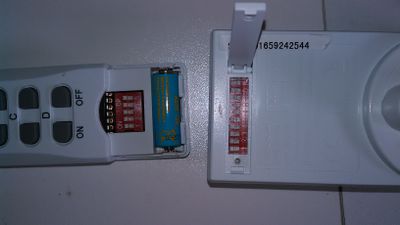
I have set up the dip switches of the remote to the system code '11111' and the socket to system code '11111', unit code '00010' (it is operated by the D buttons of the remote)
Now when I push a button of the remote I get a line like the following:
11111 10000 1
11111 10000 0
11111 01000 1
11111 01000 0
11111 00100 1
11111 00100 0
11111 00010 1
11111 00010 0
The first group of 5 bits is the code of the remote (it is the configuration of the 5 switches hidden in the battery compartment of the remote. The second group is the letter A=10000, B=01000, C=00100, D=00010 (maybe other remotes have a fifth button). The final bit is ON (1) or OFF (1).
So I can use the remote to activate any process, just by checking the pattern received.
viceversa if I type in the code of my socket in the terminal emulator followed by 1 or 0 return (CR) the trasmitter sends the code. Please note that the sketch does not echo what is typed in. When I type:
11111 00010 1
nothing appears on the terminal but the socket gets switched on, and
11111 00010 0
switches it off.
The sketch has been designed to use arduino as a device of a host computer. A daemon could parse the input lines (commands from remote controls) and trigger actions when required by the configuration. The same demon can also write the code of a socket to turn on of off as in the example above. Given this idea of usage, echoing the input would be inconsistent: the demon would receive its own commands, too.
Arduino and mm53200
Using the same modules above and the same wiring I wrote a sketch to open the gate of my garden and to receive the input from a remote control designed for garages and gates.
There is a quite common encoding (at least in Italy): MM53200. It gets its name from the integrated encoder/decoder by National Semiconductor. There are many clones like UM3750, UM86409.
The following sketch can send and receive MM53200 codes (and much more)...
/* (c) 2016 Renzo Davoli */
/* Licensed under the LGPLv2.1+ (inspired by rc-switch-2.52) */
#define MAX_CHANGES 67
#define INPUT_INTERRUPT	0
#define OUTPUT_PIN 10
#define PREAMBLE 10700
#define SHORTDELAY 300
#define LONGDELAY 590
#define NTIMES 12
#define NTIMESBF 6

unsigned int timings[MAX_CHANGES];
unsigned int changeCount;
unsigned int verbose=0;
unsigned int bfvalue=0;

unsigned char val(unsigned int timing) {
  if (timing > 250 && timing < 350)
    return 1;
  else if (timing > 550 && timing < 650)
    return 0;
  else
    return 255;
}

int decodeMM53200() {
  unsigned char code[12];
  int i;
  if (changeCount != 25)
    return 0;
  for (i=0; i<12; i++) {
    if (val(timings[2*i+1]) > 1 || (code[i]=val(timings[2*i+2])) > 1)
      return 0;
  }
  if (verbose) Serial.print("MM53200 code: ");
  for (i=0; i<12; i++)
    Serial.print(code[i]);
  Serial.println();
}

void handleInterrupt() {
  static long lastTime;
  static long duration;
  static unsigned int repeatCount;

	long time = micros();
  duration=time-lastTime;
  if (duration > 5000 && duration > timings[0] - 200 && duration < timings[0] + 200) {
    int i;
    repeatCount++;
    changeCount--;
    if (repeatCount == 2) {
      decodeMM53200();
#if 0
      for (i=0; i<changeCount; i++) {
        Serial.print(timings[i]);
        Serial.print(" ");
      }
      Serial.println();
#endif
      repeatCount = 0;
    }
    changeCount = 0;
  } else if (duration > 5000) {
    changeCount = 0;
  }
  if (changeCount >= MAX_CHANGES) {
    changeCount = 0;
    repeatCount = 0;
  }
  timings[changeCount++] = duration;
  lastTime=time;
}

void sendMM53200(int value) {
	int mask;
	digitalWrite(OUTPUT_PIN,LOW);
	delayMicroseconds(PREAMBLE);
	digitalWrite(OUTPUT_PIN,HIGH);
	delayMicroseconds(SHORTDELAY);
	for (mask=1<<11; mask; mask>>=1) {
		if (value & mask) {
			digitalWrite(OUTPUT_PIN,LOW);
			delayMicroseconds(SHORTDELAY);
			digitalWrite(OUTPUT_PIN,HIGH);
			delayMicroseconds(LONGDELAY);
		} else {
			digitalWrite(OUTPUT_PIN,LOW);
			delayMicroseconds(LONGDELAY);
			digitalWrite(OUTPUT_PIN,HIGH);
			delayMicroseconds(SHORTDELAY);
		}
	}
	digitalWrite(OUTPUT_PIN,LOW);
}

void sendcode(int value, int times) {
	int i=times;
	if (verbose) Serial.println(value, BIN);
	while (i--)
		sendMM53200(value);
}

void bruteforce(void) {
	for (; bfvalue<4096; bfvalue++) {
		if (Serial.available()) break;
		sendcode(bfvalue,NTIMESBF);
	}
	bfvalue &= 0x3ff;
}

void inbyte(int inchar) {
	static int value = 0;
	switch (inchar) {
		case '\r':
			sendcode(value,NTIMES);
			value=0;
			break;
		case 0x02:
			bfvalue=value;
		case 0x03:
			bruteforce();
			break;
		case 0x16:
			verbose = 1 - verbose;
			if (verbose)
				Serial.println("verbose");
			break;
		case '1':
			value = (value<<1) + 1;
			break;
		case '0':
			value <<= 1;
			break;
	}
}

void setup() {
	Serial.begin(115200);
	attachInterrupt(INPUT_INTERRUPT, handleInterrupt, CHANGE);
	pinMode(OUTPUT_PIN, OUTPUT);
	digitalWrite(OUTPUT_PIN,LOW);
}

void loop() {
	while (Serial.available()) {
		inbyte(Serial.read());
	}
}
A user (or a deamon) can interact with the sketch using a terminal connection.
screen /dev/ttyUSB0 115200
When a signal of a remote control using MM53200 encoding is received its code appears on the terminal. To send a code, just type in a 12 bit binary number (no echo) followed by CR,
For example if you have a gate in your parking lot and the code of your remote is '100100100100' (ie. the dip-swithes are set to on-off-off-on-off-off-on-off-off-on-off-off). When you push the remote button you'll see on the terminal
100100100100
... and the gate will open, if you are close enough. Now if you are close to the gate and you type 100100100100 (followed by return) nothing appears on the screen but the gate will open.
ctrl-v turns on and off the "verbose mode": it prints some more log messages. ctrl-b starts a brute force scan of the codes. If you type a code followed by ctrl-b the scan starts from that code, otherwise from zero. A scan can be stopped by typing any key (e.g. space) and can be restarted typing ctrl-c.
It is possible to use the sketch on other frequencies, e.g. 315Mhz or 330Mhz, using the RX TX modules for the required frequencies.
Please note that a misuse of the code above can be considered to be a crime. Technical ability and legal possibility are independent concepts (otherwise nobody would be allowed to sell knives)
Raspberry PI TX for mm53200
Following this series of experiments on radio remote controls I generate MM53200 encoded signals using a Raspberry PI and nothing else but a wire (used as an antenna).
I got inspiration from the code Minimal clock access published here: http://abyz.co.uk/rpi/pigpio/examples.html.
Please note that this is just a proof of concept. Without additional filters this program may generate interferences in restricted bands. I take no responsability for the problems created by an improper use of this program. The usage of this program might be illegal in your country or might require a HAM-radio license.
In fact, the program uses the harmonics generated by the square wave of a frequency programmable clock signal. Square waves generate very strong harmonics. A filter would be required to select just the required frequency.
It is well explained in this site: http://www.skagmo.com/page.php?p=projects/22_pihat
The code is here: http://www.raspibo.org/renzo/mm53200.c.
Compile it on a Raspberry PI and connect a 17.3 cm wire on GPIO4.
gcc -o mm53200 mm53200.c
sudo ./mm53200 100100100100
the second command sends the MM53200 code. The range may be shorter than a real remote, but the command should work as a remote control having the same configuration of on-off dip-switches depicted in the binary parameter.
It is possible to change the frequency and operate remote controlled devices on 315Mhz or 330Mhz. In the code there are optional lines commented out to change the frequency. THe length of the antenna should be changed consistently to be one fourth of the wave length.
  if ((rv=initClock(0, 0, 3, 1871, 1)) < 0)  //433.92 3rd harmonics PLLD
  //if ((rv=initClock(0, 0, 4, 3120, 1)) < 0) //315 3rd harmonics PLLD
  //if ((rv=initClock(0, 3, 3, 715, 1)) < 0) //315 fundamental PLLC
  //if ((rv=initClock(0, 0, 4, 2234, 1)) < 0) //330 3rd harmonics PLLD
  //if ((rv=initClock(0, 3, 3, 124, 1)) < 0) //330 fundamental PLLC
Raspberry PI TX for avidsen sockets
The disclaimer worth to be repeated: Please note that this is just a proof of concept. Without additional filters this program may generate interferences in restricted bands. I take no responsability for the problems created by an improper use of this program. The usage of this program might be illegal in your country or might require a HAM-radio license.
In fact, the program uses the harmonics generated by the square wave of a frequency programmable clock signal. Square waves generate very strong harmonics. A filter would be required to select just the required frequency.
It is well explained in this site: http://www.skagmo.com/page.php?p=projects/22_pihat
The code is here: http://www.raspibo.org/renzo/myRC.c.
Compile it on a Raspberry PI and connect a 17.3 cm wire on GPIO4.
gcc -o myRC myRC.c
sudo ./myRC 11111 00010 1
sudo ./myRC 11111 00010 0
the second command turns on the socket (system 11111, D=00010), and the third turns the same socket off.
Raspberry PI TX for mm53200 using GPIO and a tx module
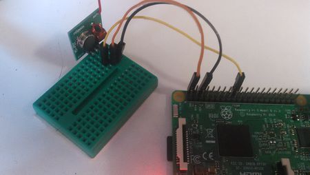
The wiring between the Raspberry PI and a TX module is:
TX has three pins
(left to right watching the component side of the PCB, there are clear labels):
   DATA <-> RPi GPIO 24
   Vcc  <-> RPi 5v
   GND  <-> RPi GND
The following picture shows the wirings:
The code is here: http://www.raspibo.org/renzo/mm53200.gpio.c
Compile it on your Raspberry PI and run it.
gcc -o mm53200.gpio mm53200.gpio.c
sudo ./mm53200.gpio 101010101010
Raspberry PI TX for avidsen sockets using GPIO and a tx module
Using the same wiring explained above it is possible to drive the radio controlled sockets.
The code is here: http://www.raspibo.org/renzo/myRCgpio.c
Compile it on your Raspberry PI run it as follows:
gcc -o myRCgpio myRCgpio.c
sudo ./myRCgpio 11111 00010 1
sudo ./myRCgpio 11111 00010 0
