A new laser cutter/engraver for my Wasp 3D printer
A new laser cutter/engraver for my Wasp 3D printer
WARNING! Playing with burning laser is dangerous! If a reflective surface redirects the beam to your eyes you can be blind for the rest of your life. So always wear proper protective glasses when playing with lasers. Protective glasses are specific for the laser wavelength: glasses for red lasers do not protect you from blueray lasers. Check the protection wavelength-range on the glasses specifications.
I bought a new 1W blueray laser from odicforce.
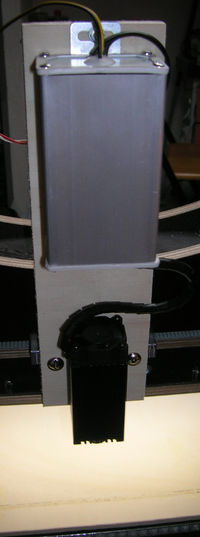
I built a wooden support for the laser module. It is just a rectangle of compensate wood having drilled holes in the correct positions. Obviously I built it using my Wasp Printer as a CNC Mill.
I had to open the control box of the laser module (the steel-gray box in the top part of the picture above) to install the TTL cable. It is the yellow/black wire-pair. Odicforce includes the cable in the package but it is not connected.
The second step was to find a way to turn on and off the laser using the G-code. My WaspProject printer uses a Ultimaker electronics board (v.1.5.3). The board has two extension sockets (ext1 and ext2) but unfortunately the connectors have not be soldered on the board. I had to unmount the board and solder the connectors. I also added a flat cable to provide an ext2 socket available outside (the 10 pin flat cable passes through the an air slot between the power switch and the usb socket).
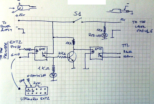
I built a control circuit for the laser. Here is the schematics.
This control circuit is connected to the ext2 socket of the Ultimaker board (via the external socket), to the 12v power supply and to the 12v and TTL input of the laser module. The NPN transistor is a BC547 or a BC548.
There are optocouplers to insulate the laser module power supply system from the voltage levels of the logical board of the 3D printer. A red diode is connected to the power supply switch of the Laser module. When the red led is on, the laser is "armed". The switch S1 "arms" the laser and turns on the red led. It is the "warning" led: when it is on everybody in the room must wear their protective glasses. The orange led means that the the laser has been turned on by the g-code. The laser beam is really burning only when the red and orange leds are both on. If the S1 switch is off (so the red led is off) it is possible to do a dry-run test. Running the G-code, the laser head will move and the orange led will show when the laser would be burning but the laser stays off as it is disabled/disarmed.
The laser can be controled by the G-code using the M42 command.
The command:
M42 P38 S255
turns the laser on, while
M42 P38 S0
turns it off.
These commands are not bufferized, so M400 is needed to synchronize moves and beam activations.
For example:
m42 p38 s0
g0 x10 y10 z50 f1000
m400
m42 p38 s255
g1 x20 f100
g1 y20 f100
g1 x10 f100
g1 y10 f100
m400
m42 p38 s0
This code draws/engraves/cuts a square. After the G0 move to the starting position I have inserted a M400 command as the laser must be turned on when the move has been completed. Then the four G1 commands print the square (the laser is on). Another M400 waits for the drawing process to terminate prior to turn the laser off. I have focused the laser for a 5cm focus, so I move the head to the z-level 50 plus the depth of the material. The speed f100 can cut paper, or engrave wood. f50 cuts a 2mm balsa wood sheet.
The text has been generated by an inkscape extension (path-to-gcode), and then edited by hand to substitute the z-axis moves of the CNC with m400/m42 commands to turn on and off the laser beam, and to wait for moves completion.
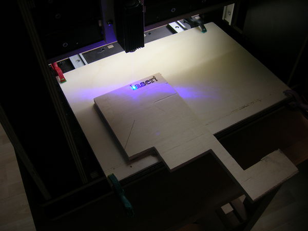
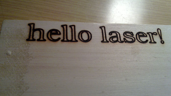
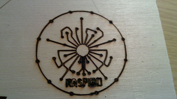
These are some results.
