No more secrets Part A: A complete ALU
An ALU is not just an adder, it is a circuit which is able to perform several kinds of computations: both Arithmetic and Logic operations. Our ALU is able to compute sums, subtractions, comparisons, and/or/not bitwise logical operations, sign change, etc.
An ALU has a number of control input line which select the operation, two sets of input lines (two buses) for the operands and an output bus for the result.
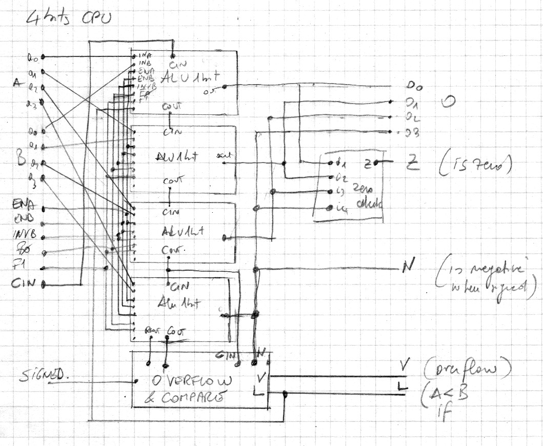
The implementation of our ALU requires three breadboard per bit plus two breadboard for zero and overflow detection. A complete four-bit ALU then requires 14 breadboards, a three-bit ALU just 11. Zero and overflow detection circuits are optional.
Do not skip this section if you don't have so many breadboards or so many friends to play with. It is possible to test each block separately and use your imagination to envision how the entire structure behaves.
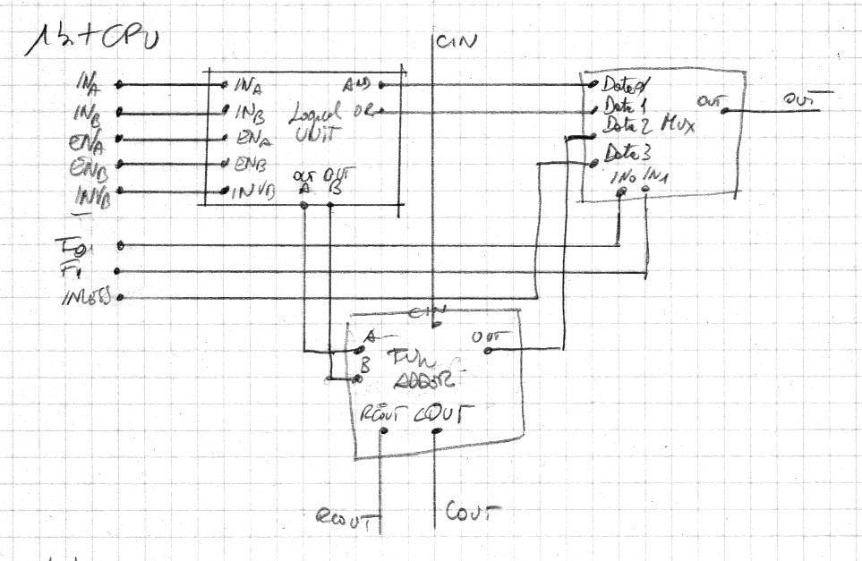
Each bit of our ALU is composed by a three breadboards: a full adder, a two-control bits multiplexer and the logical unit. We have already presented the two former circuits, the latter one is presented in the following part of this chapter.
The block schematics is the following one:
Several 1-bit ALUs can be connected/chained together. It is possible to add an overflow and a zero check circuits.
The logical unit selects which inputs are used in the computation and
performs some logical computations: 'and', 'or'.
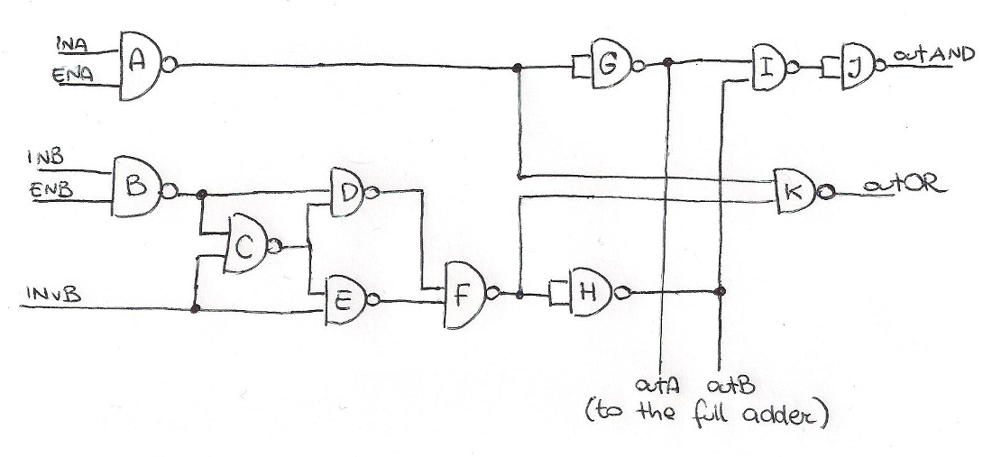
The schematics of our logical unit is in the following picture:
This is the map of the jumpers:
inA -> A
enA -> A
inB -> B
enB -> B
invB -> CE
A -> GGK
B -> CD
C -> DE
D -> F
E -> F
F -> HHK
G -> I,outA
H -> I,outB
I -> JJ
J -> outAND
K -> outOR
This circuit has two data inputs: inA and inB. These inputs get the value of two corresponding bits to be processed.
There are three control input bits: enA, enB and invB. The prefix 'en' means 'enable': if enA is zero the value of inA is ignored, discared, i.e. inA is taken into consideration for the computation only when enA is true. When enA is zero the first operand of the full adder, of the 'and' operation , of the 'or' operator is zero. Similarly enB is the enable bit for inB. When invB is one the value of B is negated. So when enB is 1 the input for the second operand of the full adder and of the logical operators (and, or) is B, or not B when invB is 1. If enB is zero, the input of that second operand has the same value of invB.
So, outA and outB have been pre-processed to be the inputs of the full adder.
inA inB invB outA outB    outAND     outOR
 0   0   0    0    0        0          0
 0   0   1    0    1        0          1
 0   1   0    0    B        0          B
 0   1   1    0  notB       0        notB
 1   0   0    A    0        0          A
 1   0   1    A    1        A          A
 1   1   0    A    B      AandB      AorB
 1   1   1    A  notB  Aand(notB)  Aor(notB)


