Differenze tra le versioni di "Arduino NANO + 19 resistors = A DDS signal generator"
Jump to navigation
Jump to search
m |
|||
| Riga 1: | Riga 1: | ||
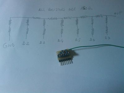
This is the schematics and the prototype... | This is the schematics and the prototype... | ||
| − | [[ | + | [[File:DDSnanosch.jpg|400px]] |
It generates signals (very nice to 1300 hz, acceptable to 10khz) using a N - 2N resistor ladder DAC. | It generates signals (very nice to 1300 hz, acceptable to 10khz) using a N - 2N resistor ladder DAC. | ||
| Riga 7: | Riga 7: | ||
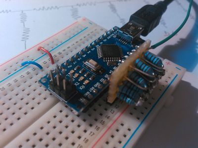
It has been designed to be plugged on 7 contiguous pins (GND, D2, ... , D7). | It has been designed to be plugged on 7 contiguous pins (GND, D2, ... , D7). | ||
| − | [[ | + | [[File:DDSnano.jpg|400px]] |
Using 150ohm resistors its internal resistance of 150ohm. It generates 0 to Vcc (actually 63/64 of Vcc) waves on an open circuit, | Using 150ohm resistors its internal resistance of 150ohm. It generates 0 to Vcc (actually 63/64 of Vcc) waves on an open circuit, | ||
Versione delle 10:10, 30 mar 2018
This is the schematics and the prototype...
It generates signals (very nice to 1300 hz, acceptable to 10khz) using a N - 2N resistor ladder DAC.
It has been designed to be plugged on 7 contiguous pins (GND, D2, ... , D7).
Using 150ohm resistors its internal resistance of 150ohm. It generates 0 to Vcc (actually 63/64 of Vcc) waves on an open circuit, 0 to Vcc/2 on a 150 ohm Load
The source code of the Arduino's sketch is:.

