No more secrets Part 5: Mux Demux
The MUX (or Selector)
The Multiplexor (also called Mux or Selector by closer friends) is a circuit which has n control inputs, 2^n data inputs and une output.
The control input decides which data input is copied into the output all the other inputs are simply ignored.
In my mind a Mux is similar to a track switch on a railroad. More specifically it reminds the switching system for the trains leaving a station. There are plenty of platforms in the station and the switches must be set up for the departing train to guarantee the routing to the railroad to the next station
The truth table for a mux having two control inputs is the following
c1  c0  in0 in1 in2 in3 out
0   0   0   x   x   x    0
0   0   1   x   x   x    1
0   1   x   0   x   x    0
0   1   x   1   x   x    1
1   0   x   x   0   x    0
1   0   x   x   1   x    1
1   1   x   x   x   0    0
1   1   x   x   x   1    1
(where x means for any value of this input, both 0 and 1)
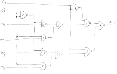
The circuit is the following:
ANd this is the file for the jumpers:
c0: AACF
c1: HHJ
in0: B
in1: C
in2: E
in3: F
A: BE
B: D
C: D
D: I
E: G
F: G
G: J
H: I
I: K
J: K
K: out
For each configuration of in0 and in1 the corresponding input will be copied to the output. To test this circuit, plug in a led to the output gate (K) and set both c0 and c1 to 0, now the led is turned on and off by setting on and off in0. In other words, in0 is copied on out. Any input on in1, in2 or in3 does not change the value of out. Now if you set c0 to 1, in1 is copied to out. Now the values at in0 in1 and in3 are irrelevant, while the led turns on and off when the input at in1 changes. Similarly when c0 and c1 are 1 0, in2 is copied and when c0 and c1 are 1, 1 is the turn of in3.
The Demux
A demultiplexer is the opposite of a mux. It takes one data input and n control inputs and 2^n output lines. The input is copied on the output line addressed by the control input.
A demux is conceptually similar to a railroad switching system, this time the one that the trains use entering a station. A train coming from a railroad is routed to a specific track to reach a specific platform where people can get on and off.
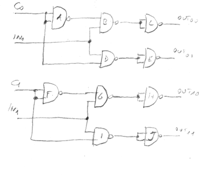
Unfortunately it needs 14 nand gates to create a two control inputs demux circuits, two more than those available on out breadboard. However, It is possible to build two 1 control bit demuxes.
This is the table to set up the jumpers on the breadboard:
c0: AAD
in0: BD
c1: FFI
in1: GH
A: B
B: CC
C: out00
D: EE
E: out01
F: G
G: HH
H: out10
I: JJ
J: out11
To test this circuit plug in 4 leds to the output lines and connect four buttons to its inputs. If you push and release the button connected to in0, out00 will turn on and off in the same manner. Now push and keep pressed the button connected to c0. The value of in0 will be copied on out01, I mean now the led on out01 instead of out00. The same experiment can be done using in1 and c1 as inputs and out10, out11 as outputs.
If you have two breadboards (or a friend has one) and you have both build this circuit it is possible to plug the two boards together and get a 2 control bits (four data outputs) demultiplexer (plus a spare 1bit demux). Connect out00 and out01 of the first board to in0 and in1 of the second and connect c0 and c1 together. The input of in0 of the first board will be routed on out00, out01, out10 and out11 depending on the value given to in0 of the first board and in0-in1 of the second.
The next chapter will describe in details how the circuits implemented on several breadboard can be connected to obtain more complex circuits.


