DCFake77: How to radio-control your clock by yourself
This project is composed by a DCF77 receiver (based on arduino) and a DCF77 Transmitter (based on Raspberry PI).
DCF77 is a radio signal at 77.5Khz. The transmitter is if Frankfurt. It broadcasts the synchronization signal for radio controlled watches and clocks.
Unfortunately it is getting harder and harder to get the signal from Frankfurt, as there are many sources of radio noise (e.g. several weakly designed switching power supplies).
I have built a simlpe receiver using a specific antenna and a Arduino.
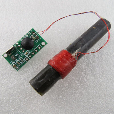
I bought my antenna on e-bay
I connected the 4 pins of tha antenna to a Arduino Nano (clone) as follows:
- PON -> +3V3
- DATA -> D2
- GND -> GND
- VCC -> +3V3
and loaded the script DCFSignal (included as an example of the DCF77 library)
/*
 * DCFSignal.ino - DCF77 debug Example
 * Thijs Elenbaas, 2012
 * This example code is in the public domain.

  This simple example shows the raw signal coming from the DCF decoder.

  Pulse-to-Pulse is approximately 1000 ms and pulse with is approx 100ms or 200ms
  The axis underestimates the elapsed time slightly, because a single loop takes a bit
  longer than 10ms.
*/

#define BLINKPIN 13
#define DCF77PIN 2

int prevSensorValue=0;

void setup() {
  Serial.begin(9600);
  pinMode(DCF77PIN, INPUT);
  pinMode(13, OUTPUT);
  Serial.println("0ms       100ms     200ms     300ms     400ms     500ms     600ms     700ms     800ms     900ms     1000ms    1100ms    1200ms");
}

void loop() {
  int sensorValue = digitalRead(DCF77PIN);
  if (sensorValue==1 && prevSensorValue==0) { Serial.println("");   }
  digitalWrite(BLINKPIN, sensorValue);
  Serial.print(sensorValue);
  prevSensorValue = sensorValue;
  delay(10);
}
Using a terminal emulator
screen /dev/ttyUSB0 115200
I get the following output:
0ms       100ms     200ms     300ms     400ms     500ms     600ms     700ms     800ms     900ms     1000ms    1100ms    1200ms
000
10
1000
100000000000
1000
10
10000000000000000
1111000
1100
11100000000000000000000000000000000000000000000000000000000
100
10000000000000000000
100000000
100000000000
1100000000
100000000000000000000000000000000000000000
100000000
10
100000000000000000000000000000000000000000000
100
100000
1000000
11000000000000000000
10000000000000000
1000000000000000000000000
.... while a "clean" output should be like this published here:
It means that the signal is very noisy so this is the reason why my radtiocontrolled clocks and watches won't synchronize with DCF-77.
DCFake77
Warning: this is just an experimental project. It may not be allowed to trasmit signals on the DCF frequency. This project should send signals received only some meters away. It would be very easy to design a power amplifier but in this case I am pretty sure you'd break some laws.
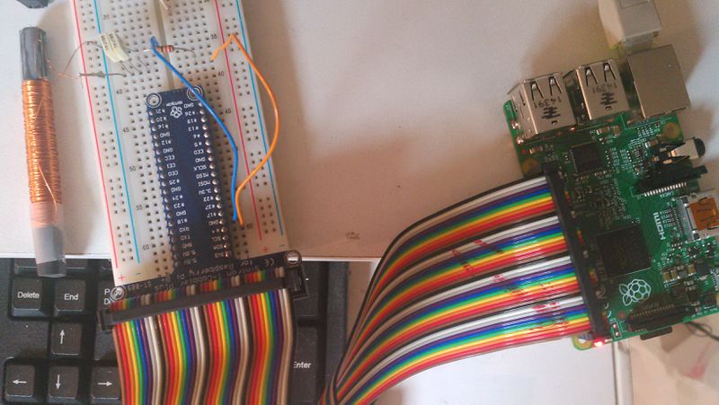
The main difficulty is to design and build an antenna for trasmitting the DCF signal. I have got an old ferrite rod (recycled from an old broken AM receiver). I wound on it a lot of turns (250?) of copper wire. I used all wire of the reel I had.
Then I used a signal generator and an oscilloscope (in my case I used my Red-Pitaya for both) and found experimentally which capacitors to put in parallel to get the right resonance frequency.
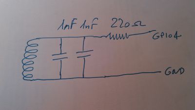
In my case it was 2nF (two 1nF capacitors in parallel).
So I connected my antenna to a Rasberry 2 as follows:
The resistor protects my raspberry if accidentally it tries to send signals out from the resonating range.
The program running on my Raspberry PI is a bit too long to stay on this page. So it can be downloaded from [1] here. It uses the clock generator on pin4.
The program needs no specific libraries so it can be compiled in this way:
gcc -o dcfake77 dcfake77.c
Dcfake77 has no command line arguments (but need access to /dev/mem, so need root access rights).
sudo ./dcfake77
At the beginning the program waits for the 59th second to start the protocol and then it sends the date and time of the following minute.
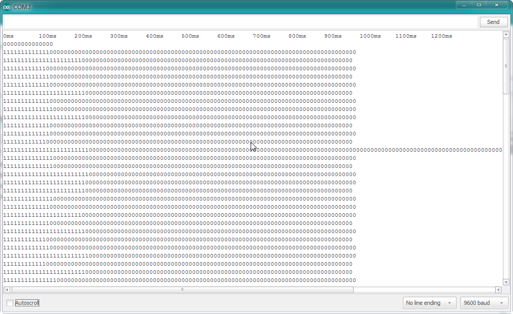
Now the output of the DCFsignal program running on arduino is consistent with the real signal of DCF77.
111111111110000000000000000000000000000000000000000000000000000000000000000000000000000000000000000
1111111111100000000000000000000000000000000000000000000000000000000000000000000000000000000000000000
111111111110000000000000000000000000000000000000000000000000000000000000000000000000000000000000000
1111111111110000000000000000000000000000000000000000000000000000000000000000000000000000000000000000
111111111100000000000000000000000000000000000000000000000000000000000000000000000000000000000000000
111111111100000000000000000000000000000000000000000000000000000000000000000000000000000000000000000
1111111111100000000000000000000000000000000000000000000000000000000000000000000000000000000000000000
111111111110000000000000000000000000000000000000000000000000000000000000000000000000000000000000000
1111111111111111111110000000000000000000000000000000000000000000000000000000000000000000000000000000
111111111111111111111000000000000000000000000000000000000000000000000000000000000000000000000000000
111111111110000000000000000000000000000000000000000000000000000000000000000000000000000000000000000
111111111111111111110000000000000000000000000000000000000000000000000000000000000000000000000000000
1111111111110000000000000000000000000000000000000000000000000000000000000000000000000000000000000000
111111111110000000000000000000000000000000000000000000000000000000000000000000000000000000000000000
1111111111100000000000000000000000000000000000000000000000000000000000000000000000000000000000000000
111111111110000000000000000000000000000000000000000000000000000000000000000000000000000000000000000000000000000000000000000000000000000000000000000000000000000000000000000000000000000000000000000000
1111111111111111111110000000000000000000000000000000000000000000000000000000000000000000000000000000
1111111111111111111110000000000000000000000000000000000000000000000000000000000000000000000000000000
111111111111111111111000000000000000000000000000000000000000000000000000000000000000000000000000000
1111111111111111111110000000000000000000000000000000000000000000000000000000000000000000000000000000
If you load on the arduino the example named DCFBinaryStream (also delivered with the DCF77 library) you'll see (after three/four minutes) that the date and time has been correctly received:
1   - binary 1 corresponding to long pulse
0   - binary 0 corresponding to short pulse
BF  - Buffer is full at end of time-sequence. This is good
EoB - Buffer is full before at end of time-sequence
EoM - Buffer is not yet full at end of time-sequence

Time: 13::00::01 Date: 27.1.2016

Time: 13::01::01 Date: 27.1.2016


