Gert's VGA board for Raspberry PI B+ using off the shelf components
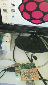
Here is my implementation of Gert's VGA board for Raspberry PI B+.
I was looking forward to testing one and I could not wait for the availability of an official PCB. So I decided to build it myself.
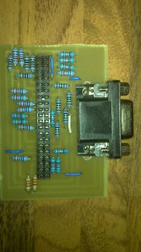
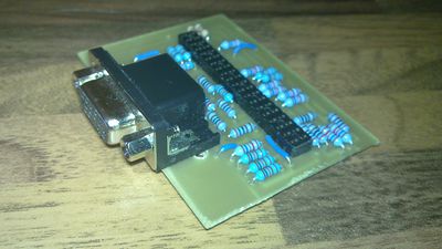
Here is the result.
I am quite lucky, there are still some shops in my town where I can buy electronic components in person. E-commerce is nice, but I prefer to ride my bike, get the components I need in a real shop as if I were buying food or stationery, and return home to solder them.
Some of the resistors listed in Gert's schematics are not EIA96 standard compliant (4K 8K and 16K) so they are not easily available. It is possible to use similar values instead: 4.02K 8.06K and 16.2K.
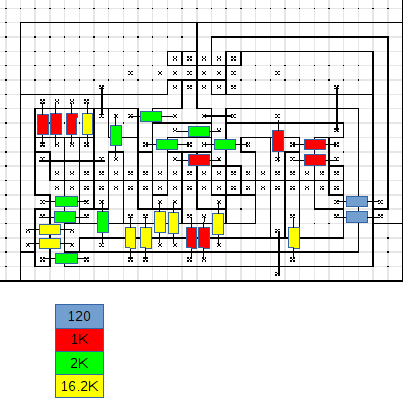
I decided to use only three resistor values 1K, 2K and 16.2K. I was told that these value are quite common, at least these are in the subset of E96 values normally available at my favourite supplier (Arduini Elettronica, Casalecchio).
The list of materials for my board is:
#9: precision resistors (1%) 1Kohm 1/4W
#9: precision resistors (1%) 2Kohm 1/4W
#9: precision resistors (1%) 16.2Kohm 1/4W
#2: resistors (5%) 120ohm 1/4w
#1: VGA PCB female connector
#1: 2x20 .1" female header
Gert's schematics implements three digital-to-analog (DAC) converters, one for each R-G-B signal of the VGA. These DACs use resistor ladders. Theoretically the values of resistors should be: 500, 1K, 2K, 4K, 8K, 16K ohm. In my prototype I used:
500ohm:  two 1K resistors in parallel (1%)
1K    :  1K resistor (1%)
2K    :  2K resistor (1%)
4K    :  two 2K resistors in series (1%)
8K    :  two 16.2 resistors in parallel (2.26% error)
16K   :  16.2 resistor (2.26 error)
The lower values need to be more precise (otherwise the DAC is not monotonic). The 1% tolerance of the 500ohm resistor generates the same error as a 32% tolerance on the 16K value.
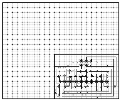
I built the PCB using my millefori program (I'll release it very soon!) I had to drill some extra holes as the mid row of pins of the VGA connector are not 0.1" aligned. (In the prototype above I had also to modify three tracks as there was an error in the PCB)
This is the PCB (as seen from the component side, the bug has been fixed).
It works like a charm.
