USB to LNB power supply: how I converted my HackRF to a spectrum analyzer to align my SAT-TV dish
A satellite dish is just a parabolic reflector, the real antenna is inside the Low Noise Block downconverter (LNB).
Satellite TV is transmitted in the Ku Band (at least in Europe, in some other parts of the world C band is used instead). More precisely the typical range of frequancy is 10.70 to 12.75 Ghz, frequencies far too high to travel inside a coax cable from an antenna to the receiver. The LNB, installed in the focus of the dish, converts the received signals in the 950-2050 range (using a local oscillator).
Universal LNBs need to receive power from the coax cable. The voltage sent to the LNB can be 13V for vertical polarization) or 18V (for horizontal polarization). Universal LNBs also have two different frequencies for the internal oscillator: 9.75 GHz or 10.60 GHz. A 22khz tone must be sent with the power to enable the higher frequency of the local oscillator.
I have a HackRF and qspectrumanalyzer is a very nice tool, but it is useless to directly plug HackRF to your LNB: without the power supply your NB is simply turned off.
So I decided to design a LNB power supply. My power supply is able to provide 13 or 18v with or without the 22khz tone and is powered from a USB socket. This makes it very handy, a power bank for portable phones can be used as a battery. This circuit could be used with a Satellite Finder (also known as satellite meter, one of those boxes with an analog or digital meter and a buzzer). Using the circuit presented in this page it is possible to go on the roof carrying this circuit a power bank and the sat-finder and nothing else. No need to carry a sat-receiver or to go back and forth to change channel on the receiver to test different bands or polarization.
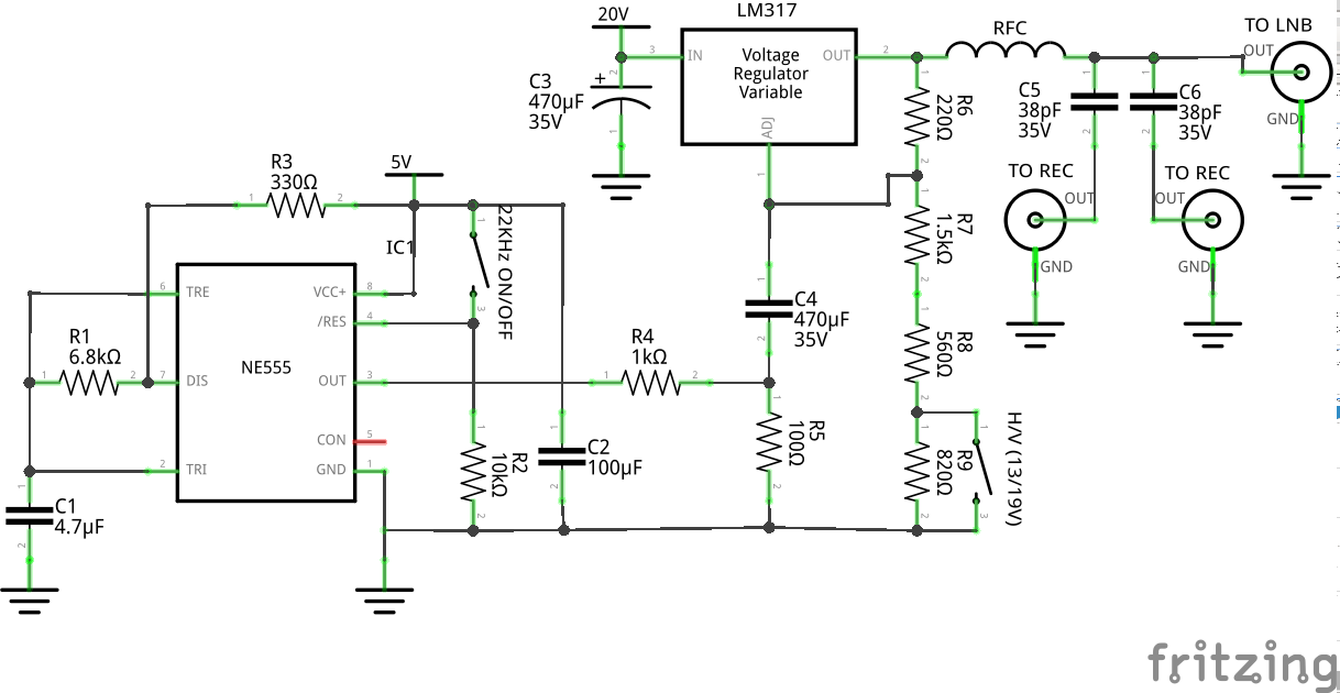
The circuit is composed by 4 sections:
- a step up switching power supply (not depicted, it is a standard circuit bought on e-bay)
- a NE555 oscillator for the 22Khz tone
- a LM317 voltage regulator to supply 13/18v (mixed with the tone)
- a shielded box with the F sockets to split power and signals.
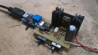
This is a picture of the prototype, the blue PCB is the step-up switching converter.
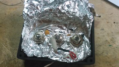
This is the shielded box (I used some aluminium foil)
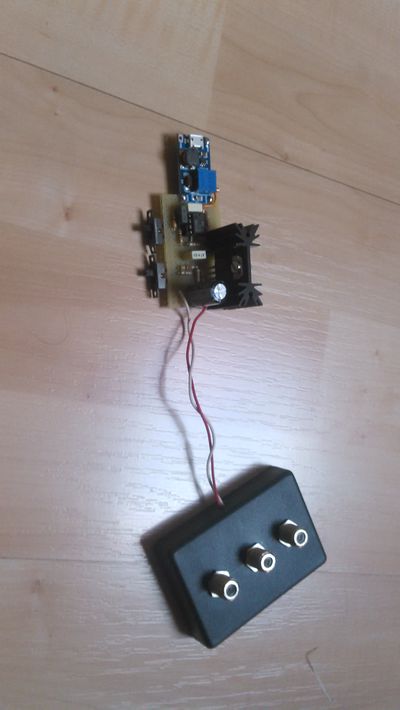
This is the entire prototype
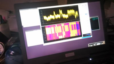
And this is an example of the spectrum received from astra 23.5E. (sorry, the picture is out of focus). It is possible to see the shape of the transponder carriers. In the waterfall there are different bands/stripes because I changed polarisation and band using the two switches.
